Introduction
A CNC milling process is rarely determined by the machine alone. Before machining starts, engineers need to understand the geometry of the part, the features that need to be created, and how the cutting tool can reach those areas while maintaining accuracy.
A single component may contain several different machining requirements. A flat surface may need to be prepared as a reference for later operations, an internal cavity may need controlled material removal, and angled or curved areas may require a different tool path or machine configuration. These different requirements are the reason why CNC milling involves multiple machining operations rather than one universal cutting method.
The selection of a CNC milling operation is closely related to how the final part will function. A mounting surface, a sealing area, a lightweight pocket, and a complex contour each have different manufacturing considerations. Tool selection, workholding, machining sequence, and machine capability all influence the final result.
For engineers working with CNC machined parts, understanding the differences between milling operations helps during both the design and manufacturing stages. It allows potential machining challenges to be identified earlier and provides a clearer way to communicate part requirements with a CNC machining supplier.
CNC Milling Operations Start With Part Geometry
The machining process usually begins with analyzing the features shown in the CAD model. Instead of asking which milling operation is the most suitable in general, manufacturers first consider what needs to be created on the workpiece.
A component with large flat areas, for example, may require surface preparation before other features can be machined accurately. Parts with internal cavities require controlled cutting paths to remove material from enclosed areas. Features such as slots, angled surfaces, and curved profiles create different challenges because the tool needs to maintain proper engagement with the material throughout the machining process.
This is why two parts made from the same material can require completely different machining approaches. An aluminum plate may only need basic milling and drilling, while an aluminum housing with internal structures may involve multiple CNC milling operations, different tools, and several machining setups.
Manufacturing considerations also extend beyond the visible shape of the part. A feature that appears simple in a drawing may become difficult to machine if the cutting tool cannot access the area, if the wall thickness is too thin, or if the setup cannot provide enough stability during cutting. These factors influence the machining strategy before production begins.
Face Milling: Establishing a Stable Machining Reference
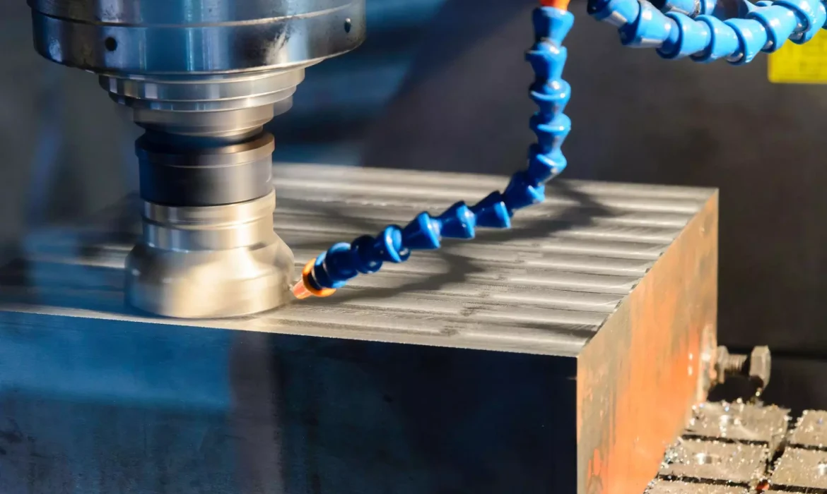
When a raw material block enters the machining process, the first challenge is often creating a reliable surface from which other dimensions can be controlled. Face milling is commonly used for this purpose because it removes material from the top surface of the workpiece and creates a controlled reference plane.
This reference surface is important because later machining operations depend on accurate positioning. Hole locations, pocket depths, and other features are often measured from established surfaces rather than from the original raw material condition.
In practical machining, face milling is frequently used on components such as mounting plates, brackets, fixture parts, and machine bases. The operation itself may appear straightforward, but achieving a consistent surface depends on several machining decisions, including cutter selection, cutting parameters, workholding stability, and material behavior.
For aluminum components, higher cutting speeds may be suitable because of the material’s machining characteristics. Stainless steel and harder alloys require different approaches because cutting forces and heat generation can affect tool life and surface quality. The machining strategy must be adjusted according to the material rather than applying the same parameters across different applications.
Learn more:The Complete Guide to CNC Milling Aluminum: Best Practices, Alloys, Tools & Pro Tips
End Milling: Creating Detailed Features Beyond Flat Surfaces
Once the basic reference surfaces are established, many components require additional features that define their function. These may include pockets, profiles, steps, and other dimensional details that cannot be produced through surface machining alone.
End milling is used in these situations because the cutting tool can remove material from both the bottom and side edges. This allows the machine to create more complex geometries while following programmed tool paths.
A mechanical bracket, for example, may require end milling to produce its outer profile and mounting features. An aluminum enclosure may require the same process to create internal clearance areas where other components will be installed.
However, successful end milling depends heavily on the relationship between the tool and the feature being machined. A small corner radius may require a smaller cutter, but smaller tools are more sensitive to vibration and deflection. A deep cavity may require extended tool reach, but longer tools reduce rigidity and can affect surface finish.
Because of these limitations, manufacturability needs to be considered during part design. Adjusting corner radii, improving tool accessibility, or changing feature dimensions can sometimes make the machining process more stable and efficient without affecting the intended function of the component.
Pocket Milling: Removing Material From Internal Areas
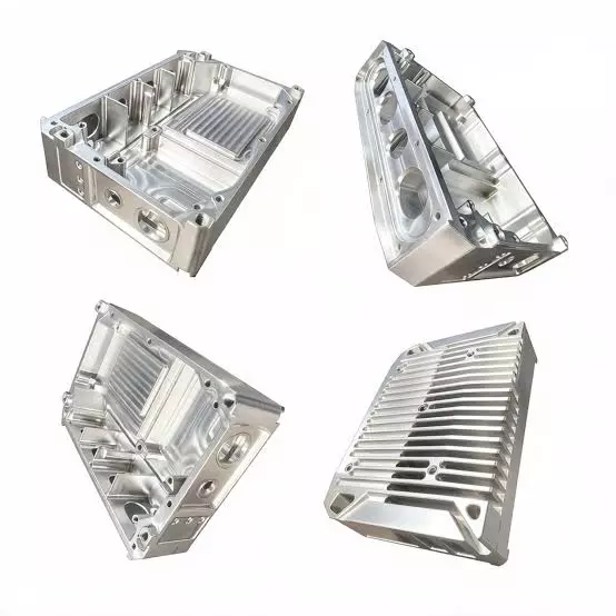
Many CNC machined parts require material to be removed from specific internal areas rather than only from external surfaces. Pocket milling is used for creating these recessed sections, allowing manufacturers to produce cavities, clearance areas, and weight-reduction features within a workpiece.
The machining challenge with pockets is not only removing material but doing so while maintaining wall thickness, dimensional accuracy, and surface quality. The tool needs to follow a controlled path inside the cavity, and the machining strategy often changes depending on the pocket depth, opening size, corner radius, and accessibility.
Aluminum housings are a common example where pocket milling plays an important role. A housing may need internal pockets to reduce weight, provide space for electronic components, or create mounting areas for assembly. Although these features may look simple in a CAD model, the machining process requires careful consideration because the cutting tool must reach the bottom of the cavity without excessive vibration.
Deep pockets create additional challenges during CNC machining. A longer tool may be required to reach the required depth, but increased tool length reduces stiffness and makes the cutter more likely to deflect under cutting forces. This can affect dimensional accuracy and surface finish, especially when machining materials that generate higher cutting resistance.
For this reason, engineers often consider pocket depth, tool access, and internal corner design during the product development stage. A design that allows reasonable tool engagement can reduce machining difficulty and improve process stability.
Slot Milling: Machining Narrow Features and Functional Channels
Slots and channels are common features in mechanical components because they are often used for positioning, guiding, sealing, or assembly purposes. Slot milling creates these narrow openings by using a cutting tool that follows a defined path through the workpiece.
Although a slot may appear to be a simple feature, its machining requirements depend on its width, depth, tolerance, and intended function. A keyway on a shaft, a guide channel on a fixture, and a clearance groove inside a component may all require different machining considerations.
Tool selection is especially important when machining narrow slots. A smaller cutter may be necessary to achieve the required width, but reduced tool diameter also means lower rigidity. If cutting conditions are too aggressive, vibration can affect slot accuracy and surface quality.
The relationship between feature design and machining capability is important here. A slot that is too deep compared with its width may require additional passes or specialized tooling. In some cases, modifying the design slightly can improve tool access and make the manufacturing process more predictable.
Contour Milling: Creating Complex Profiles and Curved Features
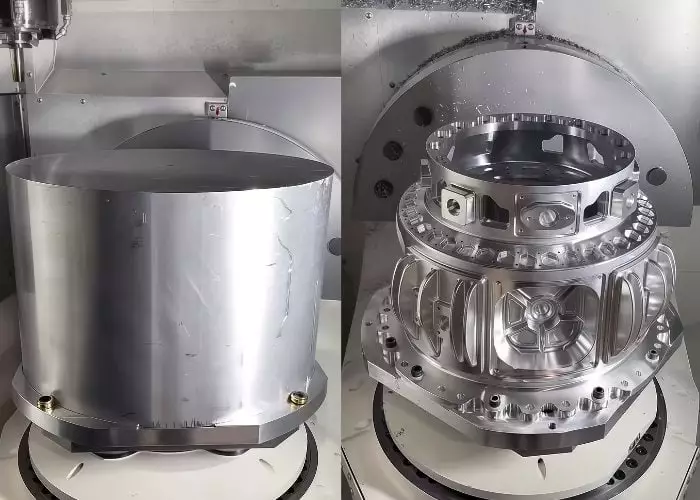
Some components cannot be produced through simple linear cuts because their functional surfaces include curves, angled transitions, or irregular profiles. Contour milling is used when the cutting tool needs to follow a specific path to create these complex shapes.
This type of machining is common in components where the external profile directly affects performance or assembly. Industrial equipment parts, aerospace structures, and custom mechanical components often include curved surfaces or complex outlines that require controlled tool movement.
The challenge with contour milling is maintaining consistent cutting conditions while the tool moves along changing geometries. Sudden changes in direction, varying material engagement, and limited tool access can influence machining stability.
CAM programming plays an important role in these applications because the tool path needs to balance machining efficiency with surface requirements. Poorly planned tool paths may result in unnecessary movements, longer cycle times, or uneven surface conditions.
For parts with more complex angles and multiple surfaces, manufacturers may combine contour milling with multi-axis CNC machining. This allows the cutting tool to approach the workpiece from different directions and reduces the need for repeated repositioning.
Drilling, Thread Milling, and Additional Operations Within CNC Milling
Although CNC milling focuses on material removal through rotating cutting tools, many machined components require additional operations during the same manufacturing process. These operations are often combined with milling to create complete functional features.
Drilling is commonly used for producing holes required for fasteners, alignment, or assembly. The position and accuracy of these holes are often related to the reference surfaces and features created during milling, which is why machining sequence is carefully planned.
Thread features may require tapping or thread milling depending on the material, thread size, and accuracy requirements. Thread milling can provide greater control for larger threads, difficult-to-machine materials, or applications where thread quality is critical.
Edge finishing operations such as chamfering are also frequently included in CNC machining processes. Removing sharp edges can improve assembly conditions, reduce damage during handling, and prepare the component for later finishing processes.
In real manufacturing, these operations are rarely isolated. A single CNC setup may combine milling, drilling, threading, and finishing steps to produce a complete part while maintaining the required relationships between features.
3-Axis, 4-Axis, and 5-Axis CNC Milling: Choosing the Right Machine Configuration
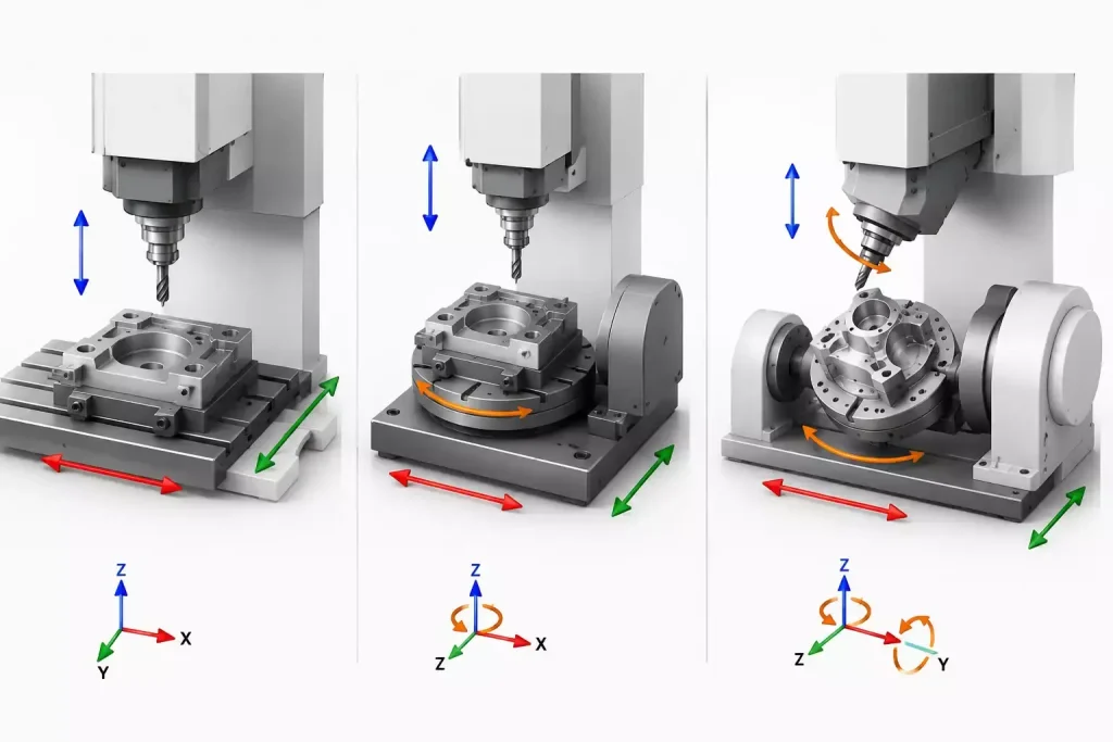
The complexity of a part often determines whether standard 3-axis machining is sufficient or whether additional axes are needed. More machining axes do not automatically mean better results; they provide additional movement options that become valuable when part geometry creates access challenges.
3-axis CNC milling moves the cutting tool along the X, Y, and Z directions. This configuration is suitable for many components where the required features can be accessed from standard orientations. Plates, brackets, and many prismatic parts can often be produced efficiently using this approach.
The limitation appears when features exist on multiple sides or at complex angles. In these situations, additional setups may be required to reposition the workpiece. Each repositioning step introduces another opportunity for alignment variation and increases preparation time.
4-axis CNC machining adds rotational movement, allowing the workpiece or cutting process to access additional surfaces without completely changing the setup. This is useful for components with features arranged around a central axis or parts that require machining from several orientations.
5-axis CNC machining provides even greater flexibility by combining three linear movements with two rotational movements. This allows the cutting tool to approach complex surfaces from different angles, which is useful for parts with deep features, angled surfaces, or complex geometries.
The decision to use 3-axis, 4-axis, or 5-axis machining depends on the actual part requirements. A simple component may not benefit from additional machine complexity, while a complex part may require multi-axis capability to achieve the necessary accuracy and reduce unnecessary setups.
How to Choose the Right CNC Milling Operation for a Part
Selecting a CNC milling operation is a balance between the part design, machining requirements, and production conditions. There is no single operation that fits every component because different features create different manufacturing challenges.
The geometry of the part is usually the starting point. A component that mainly contains flat surfaces may be suitable for face milling and standard drilling operations, while a part with internal cavities, curved profiles, or angled surfaces may require a combination of end milling, pocket milling, contour milling, or multi-axis machining.
Material selection also affects the machining approach. Aluminum alloys are commonly used for CNC machined parts because they offer good machinability and are suitable for components such as housings, brackets, and structural parts. However, materials such as stainless steel, titanium alloys, and other harder metals require different cutting strategies because they generate different levels of cutting force and heat during machining.
Tolerance requirements are another important consideration. A component used in a mechanical assembly may require accurate positioning between multiple features, meaning the machining sequence and workholding method need to be carefully planned. Reducing unnecessary setups, maintaining stable fixturing, and selecting suitable tools can help control dimensional variation during production.
Production volume also influences the choice of machining method. Prototype and low-volume parts often require flexibility because designs may still be adjusted during development. Production components may require a more optimized process where repeatability, cycle time, and consistent quality become more important.
For this reason, CNC milling process selection is not simply about choosing a machine or an operation. It requires understanding how the part will be manufactured from raw material to finished component.
Combining Multiple CNC Milling Operations in One Machining Process
Most precision machined parts are not produced through a single milling operation. Instead, different operations are combined to create the complete geometry required by the design.
Consider a CNC machined aluminum housing. The process may begin with face milling to create a reliable reference surface. End milling can then be used to produce the external profile and internal pockets, while drilling creates mounting holes and thread machining prepares connection points for assembly.
The sequence of these operations matters because each step affects the next stage of production. A poor machining order may create unnecessary setup changes or make it more difficult to maintain feature alignment. Experienced manufacturers consider the relationship between different features when planning the machining process.
This is particularly important for complex components. A part with multiple precision features may require fewer setups to maintain consistency, but reducing setups must be balanced with tool accessibility and machining requirements. The most suitable approach depends on the design rather than simply reducing the number of operations.
CNC Milling Capabilities for Custom Precision Parts
Understanding CNC milling operations is important when evaluating how a part can be manufactured, but machining capability also depends on equipment, programming experience, tooling selection, and inspection methods.
A CNC machining supplier needs to match its process capability with the requirements of the component. Standard 3-axis machining may be suitable for many mechanical parts, while more complex geometries may require 4-axis or 5-axis CNC machining to reach difficult areas and reduce repositioning.
Beyond machine configuration, manufacturing experience plays an important role in solving practical machining challenges. The ability to review part designs, identify potential issues, and select appropriate machining strategies can influence the final result.
Inspection is also part of the machining process. Features created through different CNC milling operations need to be verified against drawing requirements, especially when components involve tight dimensional relationships or assembly requirements.
For engineers developing custom components, working with a machining supplier that understands both the design intent and manufacturing limitations can help avoid problems before production begins.
Conclusion
CNC milling operations are selected based on the features a part needs rather than a fixed machining formula. Face milling, end milling, pocket milling, slot milling, contour milling, and multi-axis machining each solve different manufacturing challenges.
The most suitable approach depends on several factors working together, including part geometry, material characteristics, tolerance requirements, and production needs. A well-planned machining process considers not only how material will be removed, but also how accuracy, efficiency, and part functionality will be maintained throughout production.
For engineers and product developers, understanding these machining methods provides a better foundation for designing CNC machined parts and communicating manufacturing requirements. By considering machining processes early in the design stage, potential production challenges can be identified before they affect the final component.