
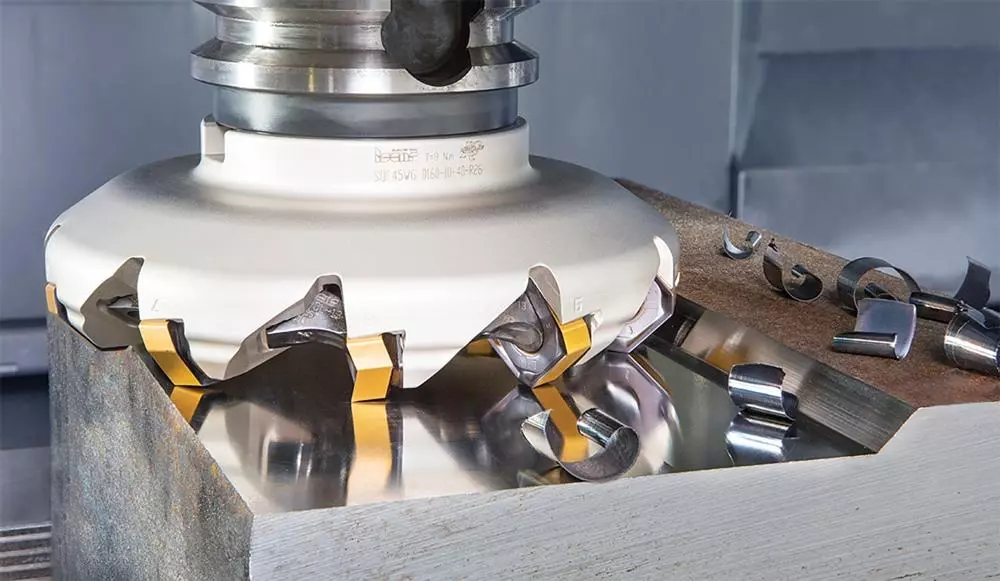
When engineers review a CNC machined part, the machining process is rarely decided by the overall shape of the component alone. The important question is what each area of the part needs to achieve.
A mounting surface may need to provide accurate contact with another component. An internal pocket may need to provide clearance for assembly. A slot may need to maintain a specific width and position. Although these features may appear on the same drawing, they create different machining requirements.
This is why the choice between face milling and end milling matters. The difference is not simply between two types of cutters. It affects how material is removed, how the part is positioned during machining, and how accurately the final geometry can be produced.
In actual CNC manufacturing, machinists usually do not ask whether face milling or end milling is better. They evaluate which method matches the feature being machined.
The Difference Between Face Milling and End Milling Starts with the Machining Goal
The easiest way to understand the difference between face milling and end milling is to look at what the operation is trying to create.
When the requirement is a controlled surface, such as a flat mounting area or a machining reference plane, the focus is on maintaining surface accuracy across an area. Face milling is commonly considered for this type of work because the cutter is designed to remove material across the face of the workpiece.
When the requirement is a specific shape or internal feature, the machining challenge changes. The cutter needs to follow a defined path, reach certain areas, and control dimensions such as depth, width, and corner geometry. This is where end milling becomes more suitable.
A simple example is an aluminum housing. The top surface where another component will be installed may need to be machined flat first. After the reference surface is established, internal pockets and mounting features can be machined based on that position. The first operation and the second operation are solving different problems.
Understanding this difference is more useful than simply remembering that one cutter machines the face and the other cutter machines the edge. The actual decision comes from the function of the feature.
Why Face Milling Is Used to Create Reference Surfaces
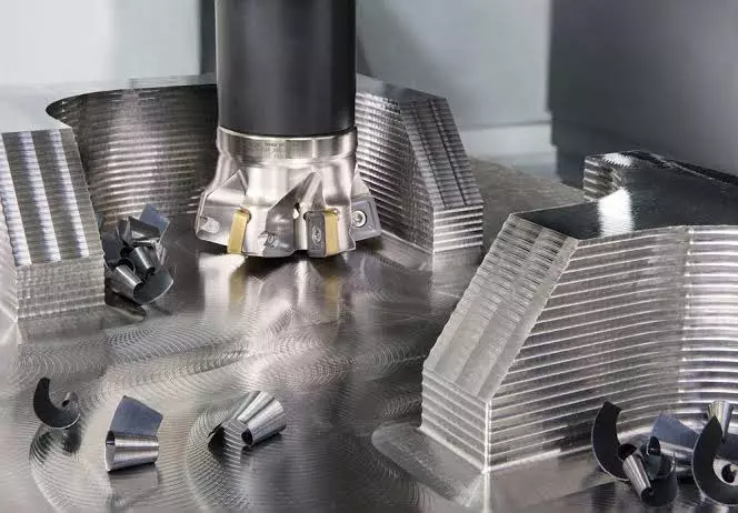
Many CNC parts begin as raw material that does not yet have the controlled surfaces required by the final design. Aluminum blocks, steel plates, and other stock materials may have surface variations from previous manufacturing processes.
Before machining precise features, manufacturers often need to establish a reliable reference.
A good example is a precision mounting plate. The drawing may contain several holes and pockets whose positions are measured from one main surface. If that surface is not properly established at the beginning, later machining operations may be affected because the part does not have a consistent reference point.
Face milling is often used at this stage because the operation is focused on controlling a relatively large surface area. The cutter removes material from the top of the workpiece and creates a plane that can be used for following operations.
However, the result is not determined by the milling method alone. Cutter diameter, machine rigidity, workholding, and cutting parameters all influence the final surface condition.
For example, a large face mill may remove material efficiently from a wide aluminum block, but if the workholding is not stable, vibration can affect flatness and surface appearance. In precision machining, the setup is part of the process, not just the cutting tool.
Why End Milling Is Used for Detailed Part Features
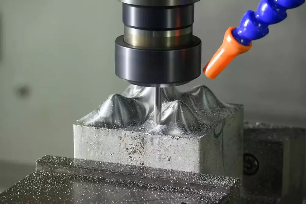
The machining requirements change when the part contains features rather than large surfaces.
A pocket inside an aluminum housing, a groove for a sealing ring, or a slot for assembly adjustment requires the cutter to reach a specific location and follow a controlled path. The challenge is not covering an area but creating the correct geometry.
End milling provides this flexibility because an end mill cutter can remove material using both the end of the tool and the side cutting edges. This allows CNC machines to create features with different depths, shapes, and profiles.
For example, a component used in industrial equipment may require a lightweight internal cavity while maintaining enough wall thickness for strength. The cavity dimensions, corner radius, and depth all need to match the design requirements. These factors influence the choice of cutter diameter, tool length, and machining strategy.
This is also why part design has a direct influence on machining difficulty. A deep narrow pocket may look simple on a drawing, but it can require longer tools, additional machining passes, and more careful control of cutting conditions.
Face Milling vs End Milling in Real CNC Part Production
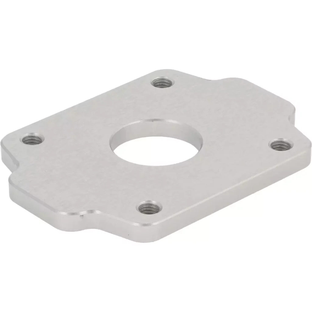
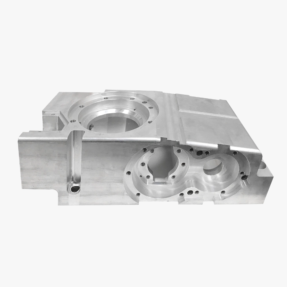
In real CNC machining, face milling and end milling are rarely treated as two completely separate processes. A finished component often requires both operations because different areas of the part have different functional requirements.
Consider a CNC machined aluminum housing. Before machining begins, the raw material needs to be positioned securely and prepared for accurate cutting. A face milling operation may be used to create a flat reference surface. This surface becomes important because later features, such as mounting holes, pockets, and counterbores, may be located relative to it.
After the reference surface is established, end milling can be used to produce the features that define how the component functions. Internal cavities may need to maintain specific depths, pocket walls may need to remain within tolerance, and mounting areas may require precise locations.
The machining sequence is not chosen only based on which cutter removes material faster. Engineers also consider how each operation affects the next one. A poorly planned sequence can create problems such as unstable workholding, difficult tool access, or difficulty maintaining dimensional relationships between features.
For example, machining a pocket before creating a reliable reference surface may make it more difficult to maintain the relationship between that pocket and other critical dimensions. Establishing the correct machining order helps ensure that each feature is produced from a controlled position.
This is why CNC machining is often a process of planning relationships between surfaces and features rather than simply removing material.
Learn more:What Are Precision CNC Machining Services and How Do They Work?
What Happens When the Wrong Milling Approach Is Selected?
Face milling and end milling are both capable machining methods, but using an unsuitable approach can create unnecessary challenges.
One common situation is using end milling for a large surface that could be machined more effectively with a face milling operation. An end mill can remove material from a flat area, but when the surface becomes larger, the machine may need more tool paths to cover the same region. This can increase machining time and may introduce more opportunities for variation between passes.
This does not mean end milling is unsuitable for flat surfaces. Small flat areas, especially those connected with other features, may still be produced efficiently with an end mill. The decision depends on the size of the area, required surface condition, and overall part geometry.
The opposite situation can also create problems. A face mill is designed for surface machining, but it is not intended for producing complex internal features. A deep cavity, narrow slot, or detailed contour requires a tool that can move through the geometry and control the cutting path.
Trying to force one machining method onto every feature can increase manufacturing difficulty. The more practical approach is to match the operation with the purpose of the feature.
How Part Design Influences the Choice Between Face Milling and End Milling
The machining decision often starts before the part reaches the CNC machine. Design choices directly affect which milling methods are possible and how efficiently they can be applied.
A pocket is a good example. From a design perspective, a pocket may appear to be a simple recessed area. During machining, however, several questions need to be considered:
How deep is the pocket?
Can the cutter reach the bottom without excessive tool length?
Are the internal corners compatible with standard end mill sizes?
Is there enough space for chip removal?
A narrow and deep pocket may require a smaller diameter end mill. However, smaller tools are more flexible and may require more careful cutting conditions. If the design allows a larger corner radius or wider opening, the machining process may become more straightforward.
The same principle applies to flat surfaces. A large uninterrupted surface is easier to approach with suitable face milling conditions. If the surface includes many small features or limited access areas, the machining strategy may need to change.
Good CNC design is not only about creating the required shape. It also considers how the cutting tool will physically reach and produce that shape.
How Material Affects Face Milling and End Milling Decisions
Material selection changes the way both face milling and end milling are performed.
Aluminum alloys such as 6061-T6 and 7075-T6 are common CNC machining materials because they provide a balance of strength, weight, and machinability. When machining aluminum components, manufacturers often focus on maintaining clean cutting conditions, controlling chips, and achieving the required surface quality.
For a large aluminum plate or housing, face milling may be used to create reference surfaces efficiently. End milling may then be applied to produce pockets, mounting features, or detailed contours.
Stainless steel creates different machining conditions. Compared with aluminum, it generally generates higher cutting forces and requires more attention to tool engagement and vibration control. The machining strategy may involve adjusting cutting parameters and selecting tooling that can handle the material behavior.
Materials such as titanium alloys and nickel-based alloys introduce additional challenges because they retain heat during cutting and can accelerate tool wear. In these cases, the machining approach often focuses on maintaining stable cutting conditions rather than simply increasing material removal.
The material does not determine the milling method by itself, but it influences how the operation is planned.
How Machinists Select Between Face Milling and End Milling
When deciding between face milling and end milling, machinists usually evaluate the complete machining situation rather than one individual factor.
The first consideration is the feature itself. Is the operation creating a reference surface, or is it producing a specific shape? This determines whether surface coverage or tool path flexibility is more important.
The second consideration is accessibility. A feature may be possible in theory but difficult in practice if the cutter cannot reach the required area without excessive tool extension or interference with other parts of the component.
The third consideration is dimensional control. Some features are closely related to each other. A mounting hole, for example, may need to maintain a precise relationship with a machined surface. The machining sequence must support that requirement.
Workholding is another factor that cannot be separated from milling selection. Thin walls, irregular shapes, or heavy cutting forces can affect how the part behaves during machining. A suitable milling approach must also work with a stable setup.
This is why experienced machinists do not select face milling or end milling only by looking at the feature name. They consider how the entire process will work from the first cut to the finished component.
Tool Selection: Face Milling Cutter vs End Mill Cutter
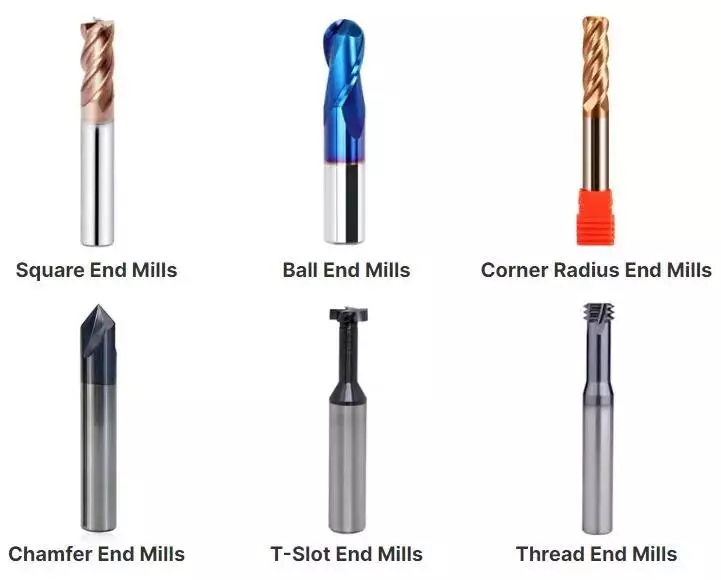
Choosing between face milling and end milling is only one part of the machining decision. The cutter itself has a direct influence on how the operation performs.
For face milling, the cutter is selected based on factors such as the size of the machined surface, material type, machine capability, and required surface condition. A larger diameter face milling cutter can cover more area during each pass, but the machine must have enough rigidity to handle the cutting forces. In precision machining, a larger tool is not automatically the right choice if the setup cannot maintain stable cutting conditions.
The insert geometry of a face milling cutter also affects the cutting behavior. Different insert designs are used depending on whether the priority is material removal, surface quality, or machining stability. Aluminum parts, stainless steel components, and harder alloys may require different cutting approaches because the material reacts differently during machining.
End mill selection involves similar considerations but is often more closely related to the geometry of the feature being produced.
A square end mill is commonly used for general pocket and slot machining because it can produce flat-bottom features and straight walls. A ball nose end mill is often used when the part contains curved surfaces or three-dimensional contours. A corner radius end mill can be useful when the design requires stronger cutting edges or smoother transitions.
Tool diameter is especially important in end milling. A smaller cutter may be necessary to reach narrow areas or produce smaller internal corners, but it also has lower rigidity compared with a larger tool. A larger cutter may provide better stability, but it may not be suitable for tight geometries.
This relationship between tool size and part design is one reason engineers often consider machining requirements during the design stage. The geometry of the component affects not only what can be machined, but also how efficiently and consistently it can be produced.
Does Face Milling Provide Better Surface Finish Than End Milling?
This is a common question when comparing face milling and end milling, but the answer depends on the machining conditions.
Face milling is often associated with flat surface machining because the cutter can create a consistent cutting pattern across a wider area. However, the final surface condition depends on more than the milling method itself.
Factors such as cutter condition, tool runout, cutting speed, feed rate, machine rigidity, and workholding stability all influence the result.
An unstable setup can affect the surface quality of a face milling operation. Similarly, an appropriate end milling strategy with suitable tooling and cutting parameters can produce accurate and smooth surfaces on smaller features.
For CNC machining, surface requirements should be considered together with the purpose of the feature. A mounting surface may require a different finishing approach from a cosmetic exterior surface or an internal functional pocket.
The important question is not which milling method produces a better surface in general, but whether the selected process can achieve the required condition for that specific feature.
Can End Milling Replace Face Milling?
In some situations, an end mill can machine areas that could also be produced through face milling. For smaller surfaces or components with limited machining areas, using an end mill may be practical.
However, replacing face milling with end milling is not always the most suitable approach.
When machining a larger surface, the choice depends on factors such as machining area, production requirements, tool movement, and machine setup. A method that works well for a small prototype may not be the same approach used for repeated production parts.
The decision should consider the complete process rather than only whether a tool is technically capable of removing material.
Should Designers Consider Face Milling and End Milling Before Manufacturing?
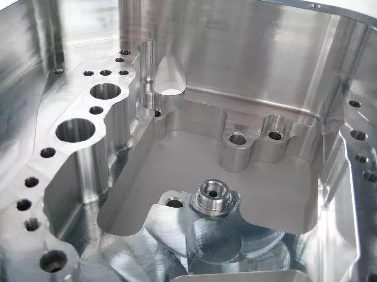
Machining considerations during design can affect the difficulty of production.
A part drawing may define the required dimensions and functions, but the geometry also determines how easily the cutting tool can access the required areas.
Features such as deep pockets, narrow slots, small internal corners, and thin walls can influence tool selection and machining stability.
For example, a pocket with very small internal corners may require a smaller end mill or additional machining steps. A deeper cavity may require a longer tool, which can introduce more tool deflection during cutting.
Design does not need to be limited by machining requirements, but understanding how CNC processes work can help engineers create parts that are easier to manufacture while maintaining the intended function.
Common Questions About Face Milling vs End Milling
Which process should be used for a CNC part, face milling or end milling?
The answer depends on the feature being machined. If the main requirement is creating a controlled flat surface, face milling may be considered. If the requirement involves pockets, slots, or complex profiles, end milling is often more suitable.
Many CNC components require both methods because different areas of the part have different functions.
Is face milling only used for rough machining?
No. Face milling can be used during different stages of production depending on the cutter, cutting conditions, and surface requirements. It can be used for removing stock material as well as producing finished surfaces.
Is end milling only for complex parts?
No. End milling is also used for simple features such as slots, holes with surrounding details, and small flat areas. Its main advantage is the ability to control the tool path and produce specific geometries.
Does the choice between face milling and end milling affect machining cost?
The machining method can influence production time, tooling requirements, and process complexity. However, cost is usually determined by the complete manufacturing plan, including material, part geometry, tolerance requirements, quantity, and finishing operations.
Conclusion
Face milling and end milling are not competing processes where one replaces the other. They are machining approaches designed to handle different types of features.
Face milling is commonly used when the primary goal is creating controlled surfaces and establishing reference planes. End milling is used when the part requires more detailed geometry, such as pockets, slots, cavities, and contours.
In practical CNC manufacturing, the choice depends on how the feature functions within the component, how the tool can access the area, and how the machining process can maintain the required dimensions and surface condition.
For engineers designing CNC parts, understanding the difference between face milling and end milling helps create more manufacturable designs and provides clearer communication with machining suppliers.
To understand how different milling processes are used in CNC manufacturing, read our guide on CNC milling operations and machining methods.