What’s CNC Precision Machining?
Let’s start with what is CNC machining. CNC machining uses computer-controlled machine tools to remove material from a workpiece based on a CAD model, drawing, and programmed toolpaths. The machine controls the movement of the cutting tool, spindle speed, feed rate, and cutting depth to produce the required dimensions and geometry.
Precision CNC machining is mainly about controlling dimensions and keeping parts consistent. Depending on the part and its requirements, tolerances may be specified at ±0.005 in. (±0.127 mm) or tighter. Tolerances around ±0.001 in. (±0.0254 mm) can also be used for suitable features when the material, geometry, machining process, and inspection method allow it. There is no single tolerance that defines every precision machined part.
This level of control is important when parts need to fit with other components or maintain a specific position during assembly. CNC precision machining is commonly used for components in automotive, aerospace, medical equipment, industrial machinery, and other applications where dimensional consistency matters.
CAD defines the part geometry, while CAM generates the toolpaths used by the CNC machine. The machine follows these paths to cut the workpiece through a series of operations until the required shape and dimensions are achieved.
What precision CNC machining means on a drawing
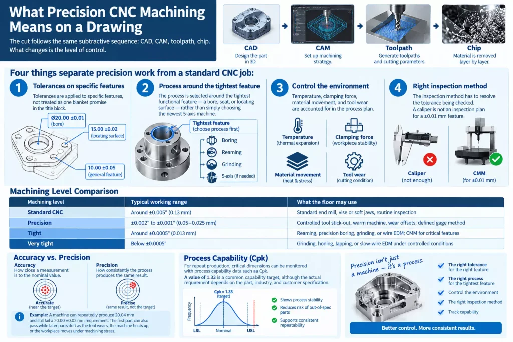
The cut follows the same subtractive sequence: CAD, CAM, toolpath, chip. What changes is the level of control.
Four things separate precision work from a standard CNC job:
- Tolerances are applied to specific features, not treated as one blanket promise in the title block.
- The process is selected around the tightest functional feature — a bore, seat, or locating surface — rather than simply choosing the newest 5-axis machine.
- Temperature, clamping force, material movement, and tool wear are accounted for in the process plan.
- The inspection method has to resolve the tolerance being checked. A caliper is not an inspection plan for a ±0.01 mm feature.
| Machining level | Typical working range | What the floor may use |
|---|---|---|
| Standard CNC | Around ±0.005″ (0.13 mm) | Standard end mill, vise or soft jaws, routine inspection |
| Precision | ±0.002″ to ±0.001″ (0.05–0.025 mm) | Controlled tool stick-out, warm machine, wear offsets, defined gage method |
| Tight | Around ±0.0005″ (0.013 mm) | Reaming, precision boring, grinding, or wire EDM; CMM for critical features |
| Very tight | Below ±0.0005″ | Grinding, honing, lapping, or slow-wire EDM under controlled conditions |
Accuracy is how close a measurement is to the nominal value. Precision is how consistently the process produces the same result. A machine can repeatedly produce 20.04 mm and still fail a 20.00 ±0.02 mm requirement. The first part can also pass while later parts drift as the tool wears, the machine heats up, or the workpiece moves under machining stress.
For repeat production, critical dimensions can be monitored with process capability data such as Cpk. A value of 1.33 is a common capability target, although the actual requirement depends on the part, industry, and customer specification.
Precision CNC vs Standard CNC
The same VMC can cut a ±0.13 mm bracket and a ±0.025 mm bore. The difference is what happens around the cut.
Standard work is built around general CNC machining tolerances, normal workholding, and routine inspection. A vise and caliper may be enough for a clearance hole or a profile that does not mate with another part.
Precision work starts with the features that locate, seal, press, or rotate. Those features need a datum that can be machined and measured, a finish pass with controlled stock, and a gage that can actually see the tolerance. If the part will be anodized or heat-treated after machining, the final size has to account for that too.
Two quotes for the same model can still look very different. Shop A may hold the unmarked dimensions to the drawing’s general tolerance and inspect the boxed holes. Shop B may treat every boxed feature as a CMM requirement or add a grinding operation for a tight bore. Neither is automatically wrong. The drawing and RFQ need to make clear which features matter and how they will be checked.
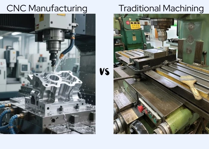
What actually eats the tolerance
CAD → CAM → clamp → cut → deburr does not explain why one supplier ships and the other sends a concession.
Thermal growth
A cold laser check is not 10 a.m. production. Ballscrews, the column, and the spindle grow as bearings come up. On many VMCs, a 20–30 minute warmup — or a short air-cut plus a probe cycle — is the difference between a depth that holds and a depth that walks 0.01–0.03 mm through the first tray. Morning-good / afternoon-out is usually heat.
Tool deflection
Treat stick-out as a spring. A 6 mm end mill at 4×D in a shallow pocket is usable. The same tool at 8×D in a 25 mm cavity will leave tapered walls and a dished floor. The part measures differently once the clamp lets go. Short tools, rest machining, and a 0.05–0.10 mm spring pass close more tight-tolerance problems than a new machine photo.
Fixture distortion
A toe clamp that kills chatter on a 6061 box can put 0.05–0.10 mm of bow into a 2 mm wall. Flatness that opens after unclamping is a fixture dimension. Soft jaws that support the opposite wall, a nest, or vacuum fix it. Turning the vise handle harder does not.
Residual stress
7075 plate, stainless, and titanium move when skin comes off. Rough to even stock — often 0.15–0.25 mm per side on aluminum, 0.10–0.20 mm on steel — then rest or age if the geometry is a known mover, then finish. One-operation “finish in the rough” looks perfect at the spindle and fails on the granite the next morning.
Heat in the workpiece
Thin aluminum and plastics grow in the cut. PEEK is the regular offender: in-process size is in family, next-morning size is not. Let PEEK and POM sit at 20 °C for a few hours, sometimes overnight, before the official measurement. A tighter toolpath does not replace that rest.
Measurement uncertainty
Use a gage that resolves about one-fifth to one-tenth of the tolerance, and do not squash the feature while you measure it. Two inspectors, two answers, is almost always method.
| Source | What you see | Floor control | When to leave milling |
| Machine / spindle heat | First 15–30 minutes drift | Warmup, probe, scales | Long travel plus tight depth |
| Tool deflection | Taper, tight corners undersize | L/D under ~4–5, light finish | Deep cavity on a small tool |
| Clamp distortion | In-fixture good, free-state bad | Soft jaws, opposing support | Thin-wall housing, plastic |
| Residual stress | Warp after rough or heat treat | Even stock, rest, finish last | 7075, stainless, titanium |
| Part heat | Plastic / thin Al shrinks later | Rest at 20 °C, then inspect | PEEK, POM, thin fins |
| Wrong gage | Arguments | Written method | Anything tighter than ±0.02 mm |
CNC machining tolerances you can put on a quote
Tight tolerance CNC machining is a cost decision, not a compliment to the drawing. Platforms that publish defaults use ±0.005” standard and ±0.001” on review. That is a planning baseline, not a promise on a 200 mm thin wall.
| Class | Relative cost vs standard | Where the money goes |
| ±0.005” | 1.0× | Normal feeds, sample check |
| ±0.002” | about +15–25% | Slower finish, more checking |
| ±0.001” | about +30–50% | Rigid fixture, CMM on criticals |
| ±0.0005” | +75–150% or more | Secondary process, full inspect, scrap risk |
Those multipliers assume a handful of tight features. A sheet that boxes every dimension at ±0.01 mm is not 30% more expensive. It is a different process.
As-machined surfaces from a finishing end mill commonly land near Ra 1.6–3.2 μm. Ra 0.8 μm is usually a dedicated finish or a grind. Calling Ra 0.4 μm on a milled pocket without grind or polish is how RFQs stall.
The choice of machining process also affects cost and part quality. See our guide to [5 Axis CNC Machining vs Traditional CNC Cost and Quality] for a closer comparison.
Feature-level expectations
| Feature | Commonly stable | Extra process or extra cost |
| Turned diameter | ±0.001” on modest OD/ID | ±0.0003” after grind or hone |
| Reamed / bored hole | ±0.0005”–0.001” in stable stock | Hardened 17-4, interrupted holes |
| Milled pocket / slot | ±0.002”–0.003” | Deep pocket, small tool |
| Hole position | ±0.002”–0.005” true position in one setup | Three flips and a weak datum scheme |
| Face flatness | about 0.002” over a few inches | Large thin plate — grind or stress relief |
| Threads | 2B / 6H default | 3B only where the function needs it |
Position is not diameter. A hole can be a perfect size and miss the cover by 0.08 mm. If the print uses GD&T, cut and inspect to the same datums.
Materials that change the number
A 100-alloy catalog is not shop knowledge. These nine change how size is held.
6061-T6. Fast. Tight features fail from clamps and stick-out more than from the alloy. Type II anodize is often 5–25 μm per side. Type III hard coat is commonly 25–50 μm per side (about 0.001”–0.002”). A hole that must be ±0.01 mm after coat is not finished to the print number before coat.
7075-T6. Stronger, more stressed plate. Rough evenly, then finish. Treat it like slow 6061 and you will chase flatness.
304 / 316. Work-hardens. Stay in the cut with a sharp tool. On a 50-piece run the drill or bore tool picks up 0.01 mm of wear if nobody offsets. That is a wear problem, not a controller-resolution problem.
17-4PH. Condition is the job. H900 is not annealed plus hope. Finish after heat treat, or leave grind stock on the seats.
4140. Fine when the heat-treat state is on the traveler. After harden, the precision seats leave the mill and go to grind.
Ti-6Al-4V. Heat stays in the chip. Low surface speed, sharp edge, rigid setup. A long cycle that ignores heat will grow a bore through the batch.
C360 brass. Size is easy. Burrs and edges are the fight.
POM (acetal). Cuts clean, then moves with temperature and moisture. Official size at 20 °C after a rest.
PEEK. Scrap is expensive. Heat and residual stress dominate. Tight plastic features need hours on the rack, not only a smaller CAM tolerance.
Plasma and commodity laser cutting do not belong here. They are valid processes. They are not how a bearing bore is held. Wire EDM and sinker EDM do belong: hard profiles, inside corners sharper than a cutter radius, slots a mill will bend.
Pick the Process from the Part
Precision CNC turning is the natural choice for diameters, concentricity, and faces that need to stay square to an axis. A lathe will usually hold a round journal more consistently than a mill interpolating the same circle, especially when that journal has to run in a bearing.
Precision CNC milling is better suited to pockets, hole patterns, and prismatic faces. Three-axis is often enough when the tight features can be reached in one or two solid setups.
5-axis CNC machining earns the extra cost when multiple setups would stack up location error, or when a compound angle is difficult to fixture cleanly. It is not another name for tighter tolerance. A 5-axis machine with 150 mm of tool stick-out can lose the fight against a rigid 3-axis setup with a dedicated fixture. The real advantage of 5-axis is fewer datum transfers.
Use a reamer or single-point boring when hole size and roundness matter. Use wire EDM or sinker EDM for hardened material, sharp internal corners, or features that are difficult to cut conventionally. Grind or hone sealing faces and bearing journals when the final tolerance or surface finish calls for it. A finishing end mill is not always the right tool for the last few microns.
Quote gate
- What is the tightest functional tolerance?
- Can the feature be finished in one clamp relative to the CMM datum?
- Will the material, heat treatment, or coating change the final size?
- Can the feature be measured with a gage that actually resolves the specification?
- If not, change the process or change the print.
Same callout, different shop: ±0.01 mm on a hole in 6061 may call for a reamer and bore gage. The same tolerance in 17-4 H900 may push the process toward grinding or wire EDM.
A Sequence That Still Measures After the Vise Opens
Drawing review. Mark the features that actually assemble to something else. A print with twenty dimensions at ±0.01 mm is not automatically a precision print; it may just make the whole part expensive to build. Put the tighter tolerance where the function needs it and leave non-critical dimensions at the appropriate general tolerance. Also check true-position callouts. You cannot hold a tight position if the datum features themselves are allowed to move.
Stock. Leave enough material for the finish pass, but not so much that the tool has to fight the part. For aluminum pockets, 0.15–0.25 mm per side can be a reasonable starting point; steel may be closer to 0.10–0.20 mm depending on the operation. The actual allowance comes from the material, tool, geometry, and depth of cut.
Last pass. Keep the chip load consistent and the tool stick-out short. Collision simulation tells you whether the tool hits the part. It does not tell you how much the tool or workpiece will deflect. A 2 mm wall can move.
First article on a warm machine. A first article measured on a cold machine is not a good picture of the process you will run in production. Bring the machine to operating temperature, then probe or measure the critical features. If something is off, change one variable at a time — tool, fixture, offset, or program.
Coat and heat treat. Anodizing adds material to the surface and can affect holes and fits. Heat treatment can move the part itself. Either leave the right allowance and finish afterward, or compensate in the machining process and verify the final dimensions after treatment. A clean as-machined inspection report can still fail incoming inspection if the finished part has moved out of tolerance.
Inspection is part of the process
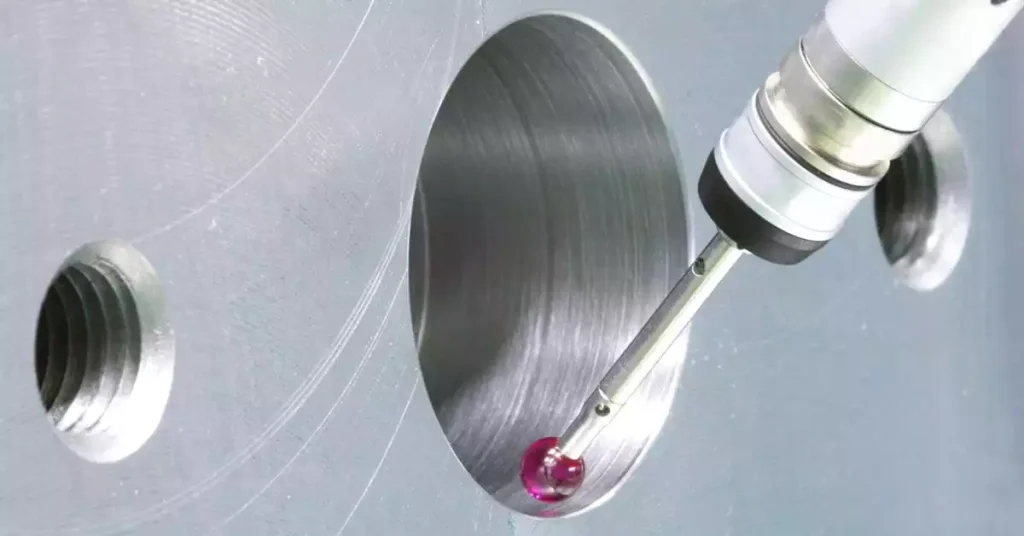
A tolerance without a method is a preference.
| Tolerance | Not the final judge | Use |
| ±0.1 mm | — | Caliper |
| ±0.02–0.05 mm | Caliper alone | Micrometer, height gage, pins |
| ±0.01 mm, position, profile | One hand measurement | CMM or a designed fixture gage |
| Roundness, small bores | Two-point mic only | Air gage, form, or a CMM strategy |
Write temperature (20 ±2 °C), plastic rest time, and which points represent a hole before the first chip. Record actuals on the features that can stop an assembly. A certificate on the wall is not a report on the bore.
Where Precision Machined Parts Fail in the Assembly
You do not need turbine blades, stents, or satellite panels to see a precision machining problem. The precision machined parts that fail on a receiving dock usually fail in much more ordinary ways.
Bearing bores and press fits. Size alone is not enough. A bore can measure correctly at two points and still be out of round. Bore or ream when appropriate; grind when the material and tolerance call for it.
O-ring glands. Width, depth, and flatness matter more than a decorative Ra note. A dished gland floor can leak even when the surrounding surface looks good. Measure the gland itself, not the nearby wall.
Dowel patterns. Every hole can be within its individual tolerance and the cover can still refuse to drop on. That is a position problem. If the pattern is critical, machine it in one setup whenever the geometry allows.
Thin plates next to rails or optics. Flat on the mill does not always mean flat in the assembly. Residual stress, machining sequence, and anodizing can change the part. Check free-state flatness when the part has to sit against a rail, optic, or reference surface.
Mechanism fits. The gap is part of the design. A burr is not. It can become a wear particle, change the fit, or stop a mechanism from moving. Deburring is a process, not a wipe with a cloth.
Two patterns from the floor
Composite jobs, not named accounts.
A 6061 multi-cavity housing held location on the first article and lost 0.04–0.06 mm of true position after the third flip. Keeping the critical hole pattern in one setup did more than changing cutting speed. The numbers only settled when the CMM used the same datums as the fixture.
A 316 spool was in family straight off the mill and moved after sitting. The sealing diameters had been finished while the part still wanted to move. Rough, let it stabilize, finish, then grind the seats. The CMM became boring. That is the goal.
How to read a quote
Ask for capability by feature and material, not one best-case number. Ask whether first article and production share the path, including coating. Ask which secondary operations leave the building. Ask for a redacted CMM page on work that looks like yours.
Put three lines on the RFQ so two prices mean the same thing:
- default standard for unmarked dimensions
- the short list of features that must be reported
- sizes before or after anodize / heat treat
A useful filter: will they tell you what they cannot hold on this geometry. A supplier that claims ±0.001 mm on every face of every alloy is selling a number.
Choosing a CNC Precision Machining Partner
Two main factors in deciding on a reliable precision machining partner for your components & products are technical capabilities and experience in the related industry. The company must have the CNC machines and quality control equipment to fulfill your machining requirements. Consequently, you also need to ensure the machining tolerances the manufacturer offers.
MS Machining is a China-based precision CNC machining service company with experience in automotive, aerospace, electronics, medical, industrial, and treatment plants, as well as many other industries worldwide. We can provide preciseCNC machining service tolerances as low as 0.002 inches.
The features of our precise yet cost-effective CNC machining services are;
- Multi-axis CNC machines(3, 4, and 5)
- Advanced EDM and CNC Plasma cutters
- Expert engineers & operators
- Rigorous quality control & ISO 9001 or AS9100 certifications
- Prototyping and small batch runs with flexible scalability options
- 100+ material options
- Client-centric communication and rapid lead times
Advantages of High Precision CNC Machining
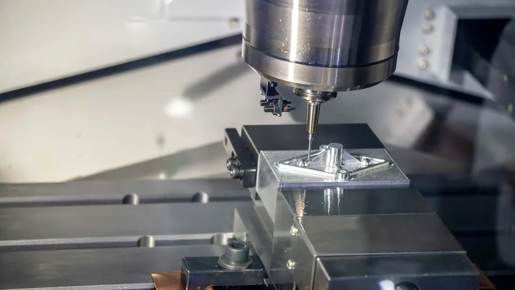
Increased Accuracy and Repeatability
The main difference between standard and precision CNC machining is accuracy. CNC precision machining equipment can run the same set of instructions to achieve tight precision and consistency across batches. This repeatability helps to ensure the production of identical parts in large volumes.
Reduced Waste and Enhanced Efficiency
The optimal tools and parameters maximize the use of raw materials and minimize off-cuts and scrap. Thus, efficient material utilization reduces waste and lowers material costs. Additionally, consistent production quality, faster machining times, and minimal defective items due to automation significantly improve overall production efficiency.
Complex Geometries with Tight Tolerances
Complex parts like turbine blades, custom implants, and molds are also precisely manufacturable using precision machining techniques. The multi-axis capability, computer control of tooling, real-time monitoring & adjustment, and several other features allow for highly complex parts & precision machined products while maintaining tight dimensional precision.
Material Versatility
Adjusting the CNC machining variables and tooling setup allows us to accommodate various materials, from hard titanium grades to soft aluminum and plastics. Moreover, some metals and thermoset composites are also compatible. This large pool of CNC material options facilitates choosing the best-fit material for a particular application needs.
Flexibility in Production
The CNC precision machining techniques, milling, turning, drilling, and EDM, are flexible with the production volume, whether you need a few prototypes or large-scale runs. Consequently, the just-in-time manufacturing strategy can reduce custom parts’ setup, tooling, and machining time.
Key Applications and Industries of CNC Precision Parts
Precision machined parts show up wherever a few hundredths of a millimeter can affect how an assembly fits, seals, moves, or holds its position. The part does not have to be exotic. A bearing housing, valve body, mounting plate, sensor bracket, or medical instrument can all have a few features that need much tighter control than the rest of the part.
In aerospace and automotive assemblies, precision CNC machining is often used for bearing seats, mounting interfaces, shafts, brackets, and housings where alignment matters. A hole pattern can control the position of another component; a bore can determine how a bearing runs; a machined face can set the position of the next part in the assembly.
Medical and laboratory equipment adds another layer. Small components may combine tight fits with smooth surfaces, thin walls, or complex internal features. The requirement is not simply a small tolerance. The material, surface finish, burr control, cleaning, and inspection method may all be part of the specification.
Industrial equipment uses the same principles in less glamorous parts. Pump bodies, valve components, fixtures, robotics components, sensor mounts, and machine-tool parts often have a handful of critical dimensions surrounded by ordinary ones. Precision machining makes sense where those critical features control the function of the assembly.
Plastics are also common in precision CNC work, particularly for prototypes, fixtures, covers, housings, and low-volume production parts. Materials such as POM, PEEK, and PTFE machine differently from aluminum or steel, so the tolerance on the drawing still has to be matched to the material and part geometry.
The common thread is not the industry name. It is the function of the feature. If a bore locates a bearing, a face sets an assembly height, or a hole pattern controls alignment, that feature deserves the process and inspection needed to hold it.
Materials Suitable for CNC Precision Machining
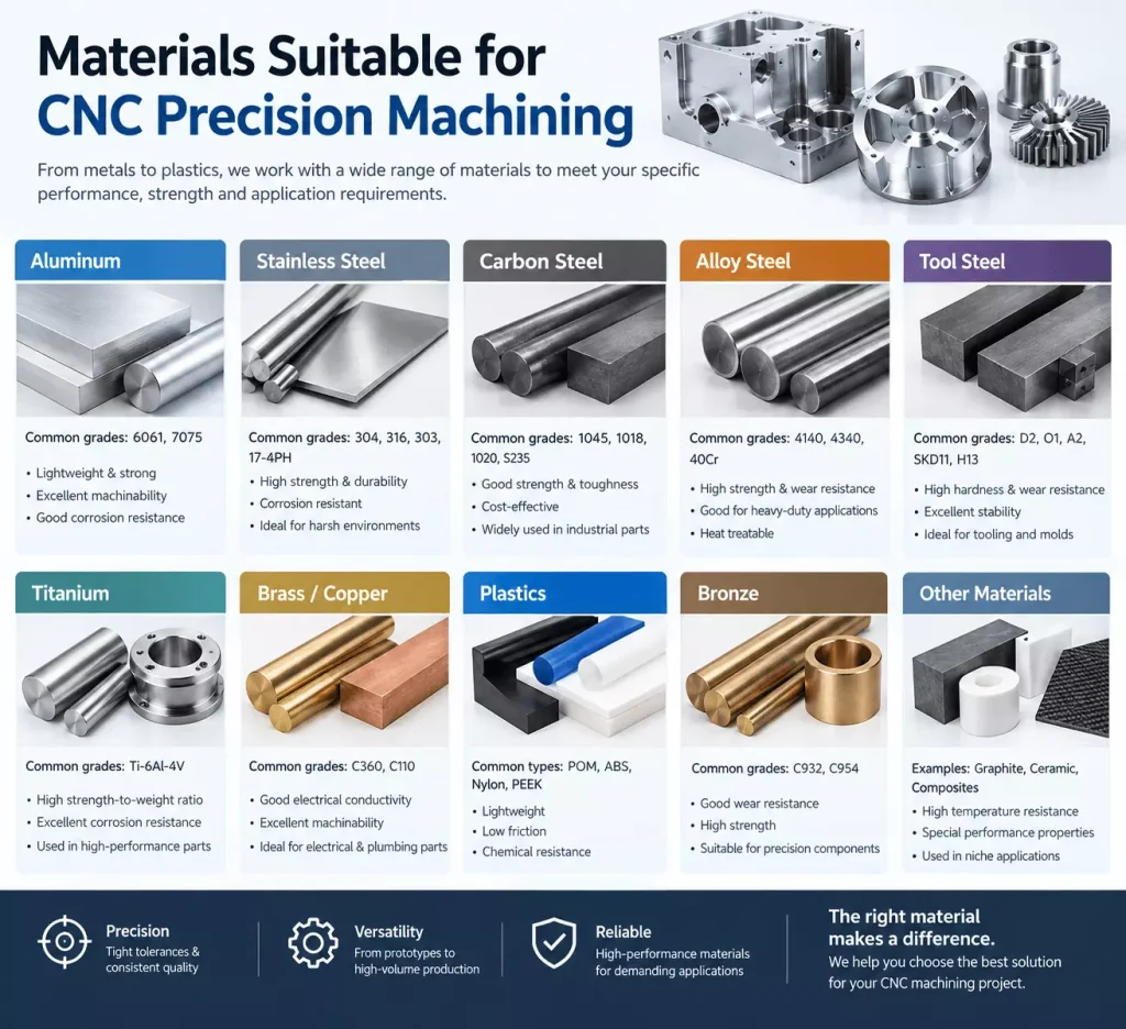
Plastics, metals, composites, and a few other materials are machineable with CNC machines. However, CNC precision manufacturing mainly deals with metals and plastics. The tooling and parameters for each CNC material are different based on its properties and machinability level.
Furthermore, suitable materials for precision CNC parts should be selected based on the required functionality of the parts and the operational environment.Material selection plays a major role in precision results, which is why MS Machining supports over 100 metals and engineering plastics with validated machining parameters.
Metals
The hardness of metals and alloys demands hard precision tools made with diamond-coated carbides. Meanwhile, consideration of thermal expansion and an efficient cooling system to counter heat buildup are essential for metal machining.
- Aluminum 6061, 7075, 2024
- Steel 1018, 4140, 1045, A2, D2,
- Stainless Steel 304, 316, and 17-4 PH
- Titanium Ti-6Al-4V
- Copper: C101 and C110
- Brass C360 C260
- Bronze C932 and C954
- Inconel 718
- Monel 400
Plastics
One of the main challenges of plastic machining is its sensitivity to heat. Therefore, production speeds are slower than those of metal machining. However, plastic CNC machining still offers dimensional accuracy and a smooth, as-machined finish. Meanwhile, the tools for plastics are standard carbide-cutting tools.
- Nylon 6, Nylon 6/6, Oil-filled Nylon
- ABS
- Polycarbonate (PC)
- Polyethylene
- Polyoxymethylene(POM) or Acetal
- PTFF & Filled PTFE (glass, carbon, bronze)
- Polyether Ether Ketone( PEEK)
- Acrylic (PMMA)
Types of Precision CNC Machines
Milling, lathe, EDM, drill, and many other machines bring precision to manufacturing. Each machine has some specific capability and is suitable for particular machining tasks. For example, a CNC lathe is ideal for symmetric items, whereas a milling machine is best for flat surfaces. Therefore, what CNC machinery is suitable for you vary on 3D designs & needed features.By combining milling, turning, EDM, and grinding under one workflow, MS Machining reduces hand-offs that often cause tolerance drift.
CNC Milling Machines
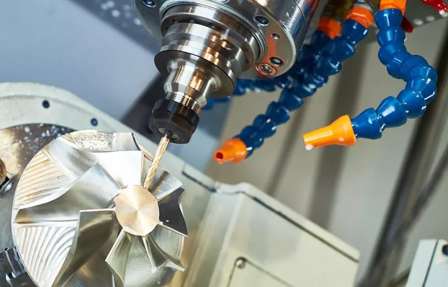
The CNC milling machine involves a rotating cutting tool, which can move along multi-axis linear and rotational motions with a liner feed of the workpiece. The spindle can rotate at high speed( up to 2400 rpm) without compromising precision and quality, as low as +/-0.0025mm. CNC precision milling can manufacture complex parts from flat and plane workpieces. Furthermore, the spindle either has a horizontal or vertical orientation. Meanwhile, some advanced mills can have both spindle orientation capabilities.
CNC Turning and Lathes
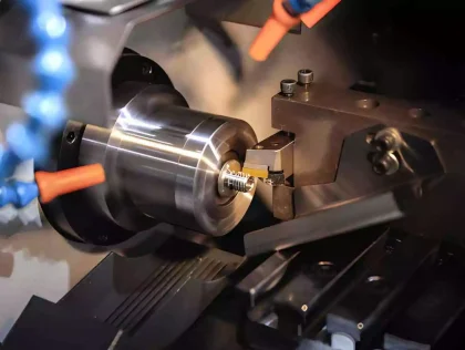
Lathes and turning machines are also part of CNC precision manufacturing. A CNC lathe or turning center rotates the workpiece, and the tool moves linearly (along and across the work) to remove and shape the material. Thus, they are used to manufacture axially symmetrical items, such as cylindrical products.
CNC Drilling Machines
The mechanism of CNC drilling involves a rotating drill bit and stationery workpiece. As the drill bit penetrates the surface, it cuts and chips away the material from the drilling area to create a hole. The drill bits are the same size as the diameter of the desired hole.
Electrical Discharge Machines (EDM)
It is the non-contact machining process that erodes the material by generating an electric spark (discharge) to create the cuts. Here, the workpiece and tool act as electrodes and create discharge due to the die-electric fluid in which they are immersed. This precision machining process exerts minimal mechanical stress and can cut through hard metals and alloys like titanium and tungsten. Moreover, EDM machines are known for their capability of manufacturing intricate shapes & details with high precision and repeatability, such as dies and molds.
CNC Plasma Cutting Machines
Plasma refers to a beam of ionized gas resulting from intense heating of air or gases up to 10, 000°c. In CNC precision machining, CNC plasma cutters use this beam to cut thermally conductive materials. The power supply unit provides high voltage to ionize the gas flowing in the plasma torch. Then, the torch focuses the plasma on the workpiece through a nozzle to melt away the material and create the cut. Unlike conventional shear or water-jet cutting, it offers exceptional machining precision. The plasma cutting tolerance can be as low as 0.001 inches.
CNC Precision Grinding Machines
CNC Grinders are post-processing equipment used in high-precision manufacturing. They contain a rotating grinding wheel with an abrasive layer of specific thickness and grain size. The machined parts are fed into the wheel to remove surface imperfections and smooth the surface by cutting the minor materials and irregularities with the abrasive. These machines are not only capable of processing the dimensions but can also provide a polished or even mirror-like finish. Precision grinders can produce a smooth surface with a roughness (Ra) value of 3.2 to 0.8 μm.
Step-by-Step Guide to the CNC Precision Machining Process
Design and CAD Modeling
After identifying the final requirements, engineers or designers create a detailed 3D engineering design containing dimensions, tolerances, features, scales, and other information. Often, computer software like AutoCAD or Solidworks facilitates CAD modeling of intended parts or products. Additionally,CNC Design for manufacturability (DMF) is a crucial consideration in this phase. The Model must be compatible with the precision CNC machining techniques.
CAM and CNC Programming
Next, CAM system software generates the instructions for tool movement based on the CAD model, called G&M codes. This process is also known as CNC programming; the codes are readable by CNC precision machines. The CAM can also simulate the optimal tool trajectory for material removal, which helps to minimize rounding errors and improve precision.
Setup of CNC Machine
The precise CNC machine setup involves two main tasks: tool setup and work holding. First, the operator installs the tool in the collet or tool holder and the workpiece on the machine bed or chuck. However, the machine can also have an Automatic Tool Changing (ATC) mechanism.
Machining the Part
The machine establishes connections with the control system to process the instructions for operation. This is the actual machining stage, where the CNC operator manually sets parameters like spindle speed, depth, feed rate, etc. Next, the machine executes the instructions, and the tools move to perform the machining of the workpiece. Meanwhile, testing for fine-tuning parameters can help produce the parts according to precision requirements.
Post-Processing and Finishing
This is the final and important step of CNC Precision Machining. The machined components might contain tool marks, burrs, or chips, affecting dimensions accuracy and aesthetic both. Post-processing methods, like grinding and deburring, can exact the required dimensions by removing minor materials from the surface. Subsequently, the finishing strategies like sandblasting, electroplating, or polishing enhance the surface quality and aesthetic. Meanwhile, some low-friction applications like hydraulic rods or rotating components require finishing for their functionality & performance.
Frequently Asked Questions
What is the difference between CNC machining and precision machining?
CNC machining refers to the automated control of machining tools via computer programs, whereas precision machining focuses on achieving highly tight tolerances and high accuracy in manufacturing parts.
How accurate is CNC machining?
CNC machining can achieve tolerances as tight as ±0.001 inches (±0.025 mm) or better. However, it heavily depends on the machine’s capabilities and the workpiece material type.
What are the types of CNC precision machines?
The common types of CNC precision machines include CNC milling machines, lathes, routers, EDMs, plasma cutters, CNC laser cutters, and grinders.
What is CNC precision machining used for?
NC precision machining manufactures high-accuracy components in various industries, including aerospace, automotive, medical, electronics, and defense—for instance, vehicle engine parts, surgical instruments, electronic housings, and custom CNC prototypes.
Is CNC precision machining expensive?
Due to its advanced technology and high accuracy, it can be relatively expensive compared to traditional machining methods. However, the long-run product reduces the per-part cost due to manufacturing speed and efficiency.
What is the difference between CNC, NC, and DNC machining?
NC (Numerical Control) machining uses punched tapes or fixed programs to control machine movements. It has limited flexibility and requires manual intervention to change machining instructions.CNC (Computer Numerical Control) machining uses a computer to store, edit, and execute machining programs. It allows higher accuracy, faster setup, and better repeatability, making CNC machining the standard for modern precision manufacturing.DNC (Direct Numerical Control) machining connects multiple CNC machines to a central computer system. Programs are sent, updated, and monitored in real time, which is ideal for high-mix, multi-machine production environments.
Conclusion
CNC precision machining addresses complexity and dimension accuracy. The automation and minimal human intervention in the operation of CNC equipment allow for stringent tolerances. Along with precision, the speed, efficiency, and customization advantages of this manufacturing strategy lower time and save costs.
You can choose this precise manufacturing for diverse applications, from medical components to electronic items. However, considering the cost factor and the necessity of high precision for operation and durability is equally important to maximize the use of technology and minimize the service price.
tolerance that cannot be measured is not a tolerance.
When you send a drawing, include datums, the default tolerance standard, and whether dimensions apply before or after coating. That package produces a number both sides can stand behind.