
Custom Sheet Metal Prototyping & Fabrication Services

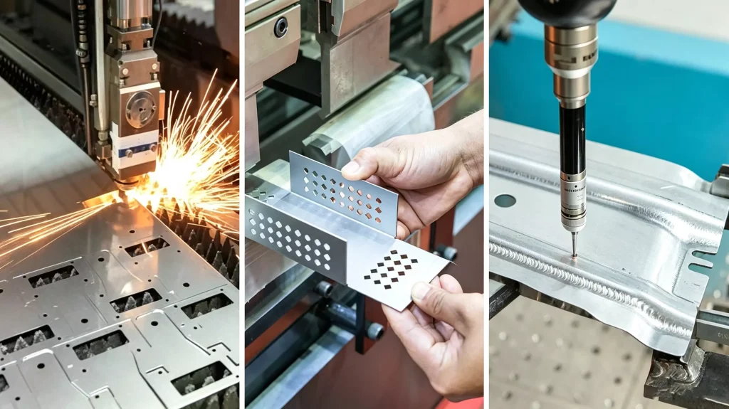
We manufacture custom sheet metal prototypes and low-volume parts from customer drawings and CAD files, including laser cutting, CNC bending, welding and surface finishing. From one-off prototypes to low-volume production, we support the same project from prototype through production.

Our Service

In-House Sheet Metal Prototype Fabrication

Your prototype starts from your drawing, not a catalog part. Our engineering team reviews material, thickness, bends, welds, hardware and finish before production. Laser cutting, forming, welding and finishing are completed in-house, with the same manufacturing capabilities available for subsequent low-volume production.

Manufacturing Process

Fiber laser cutting · CNC press brake bending · TIG / MIG / spot welding · PEM insertion · Powder coating / anodizing / plating · Dimensional inspection

Production & Quality

ISO 9001 · 1 pc MOQ · Quote Response Within 24h · Free DFM Review · Typical Prototype Lead Time: 3–7 Days

Material certificates and CTQ measurements are available on request.

Request a Factory Quote

Work email · Material + thickness · Quantity: 1–5 / 10–50 / 50–500 · Need-by date · Inspection report · Project notes

STEP + PDF preferred. NDA available. No charge to quote.

PROCESS SELECTION

Is Sheet Metal Prototyping Right for Your Part?

Sheet metal prototyping is a good fit when the final part will be cut and formed from sheet. Enclosures, covers, brackets, chassis and panels can be prototyped using the required material, thickness and bend geometry, making the prototype representative of the production part.

The manufacturing process should match the geometry and functional requirements of the finished component. Solid blocks with machined pockets, complex internal channels or deep-drawn shapes may be better suited to CNC machining, metal 3D printing or stamping.

Part Requirements & Recommended Processes
Part Requirement Recommended Process Why
Enclosure, cover, panel or chassis Sheet Metal Prototyping Suited to cut-and-bend geometry
Bracket, mount or formed frame Sheet Metal Prototyping Suitable for bends and formed features
Solid block with 3D pockets CNC Machining Better suited to material removal and machined datums
Complex internal channels or lattice structures Metal 3D Printing Allows geometries that cannot be formed from sheet
Deep-drawn or high-volume stamped shape Stamping Better suited to dedicated forming tooling

Engineering Review

If your part is designed to be cut and formed from sheet metal, prototyping it with the same material and manufacturing process provides a more representative result. If the geometry or tolerance requirements call for another process, we can identify the constraint during engineering review before production.

PROTOTYPE PARTS

Sheet Metal Prototype Parts We Manufacture

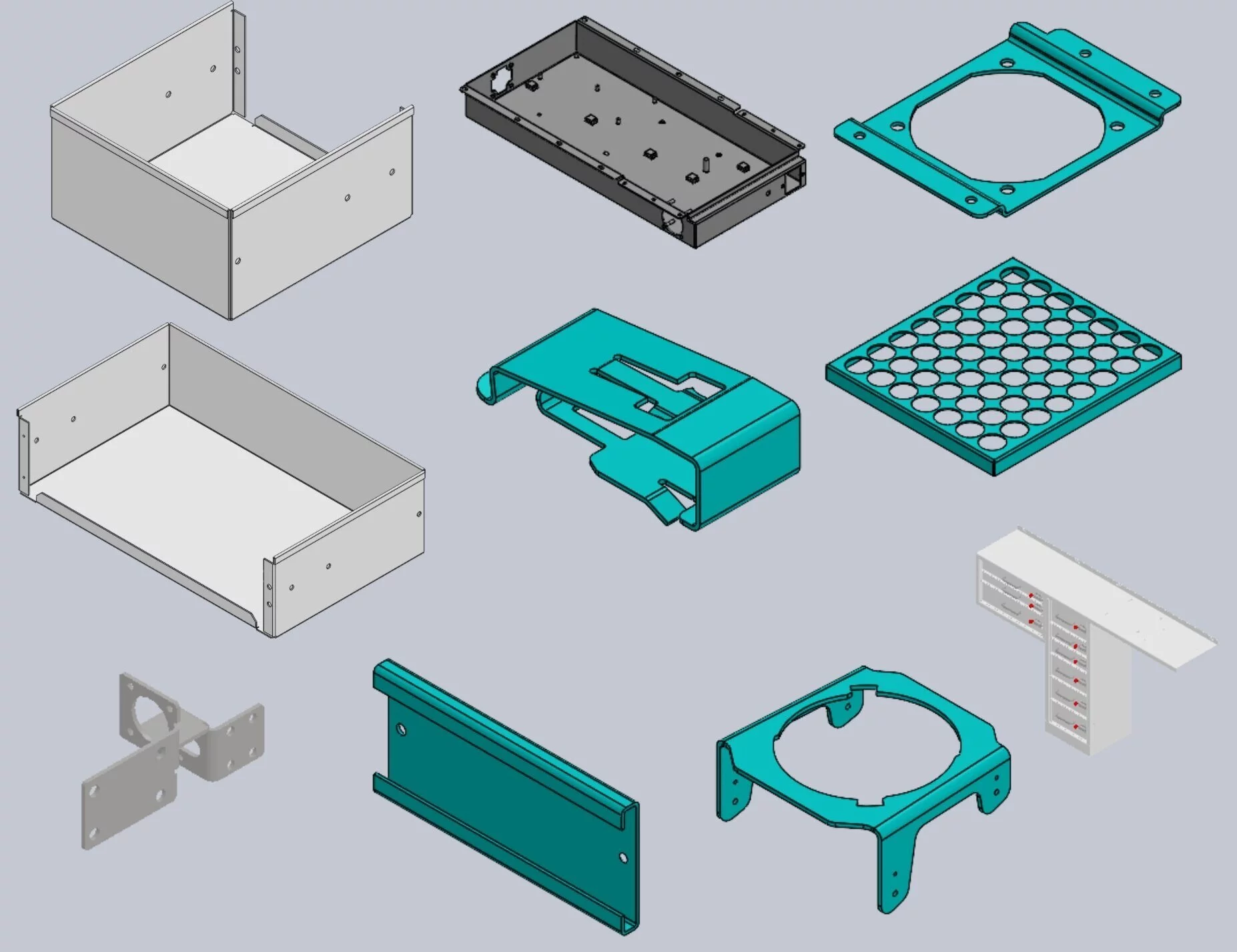
These are examples of sheet metal prototype parts we manufacture from customer drawings and CAD files. We also support custom geometries, materials, forming requirements and multi-part assemblies based on your design.

01

Enclosures, Covers and Housings

Sheet metal enclosures, covers and equipment housings with cutouts, mounting features, formed flanges and access openings. Material thickness and bend geometry are reviewed to maintain fit and clearance around internal components.
Cutouts Flanges Mounting Features
02

Brackets, Mounts and Formed Parts

Single- and multi-bend brackets, mounting plates and formed components for mechanical assemblies. Hole-to-bend distance, inside bend radius and material thickness are considered during fabrication to avoid deformation around formed features.

Hole Patterns Bend Radius Formed Features
03

Chassis, Frames and Panels

Open chassis, equipment frames and sheet metal panels with multiple flanges, offsets and mounting locations. Prototype fabrication helps verify assembly sequence, component alignment, access and fastener clearance before the design is released.

Chassis Panels Assembly Fit
04

Welded and Multi-Part Assemblies

Multi-piece sheet metal assemblies requiring TIG, MIG or spot welding. Weld sequence, joint configuration and fixturing are considered to control movement and maintain the required relationship between mating components.

TIG / MIG Spot Welding Fixturing
+

Have a Different Geometry?

These part types are examples, not limitations. We manufacture custom sheet metal prototypes from customer drawings and CAD files, including parts with different geometries, forming requirements or multi-part assemblies. The design can be reviewed before quoting to determine the appropriate fabrication approach.

Have a Sheet Metal Prototype to Build?

Send us your 2D drawing or 3D CAD file for engineering review and a prototype quote.

Upload Your Drawing
FACTORY QUOTE PROCESS

How to Get a Factory Quote

Send us the drawing package, and we review the part from a manufacturing standpoint before putting a number on it. The quote identifies the material, thickness, forming requirements, welding, hardware, finishing and critical features that affect cost and manufacturability.

01

Send the Drawing Package

Send a STEP/STP file and PDF drawing when available. Include material, thickness, finish, quantity and any CTQs or critical interfaces.

If a tolerance, bend radius, hole location or finished clearance appears likely to affect fabrication, we flag it before quoting.

Sheet metal drawing and CAD review for prototype quotation
Sheet metal prototype fabrication and inspection
02

Review the Part and Return the Quote

We review the actual fabrication sequence — laser cutting, bending, welding, hardware insertion, finishing and post-forming machining — and return the price, lead time and manufacturing notes.

03

Confirm Manufacturing Assumptions

Before production, we confirm requirements such as the inside bend radius, weld method, PEM hardware, surface finish and coating thickness.

04

Build, Inspect and Retain the Setup

We cut, form, weld, finish and inspect CTQ features before shipment. Established programs and setups can be retained for repeat quantities from 10–500 pcs.

QUOTE SCOPE

What Is Included in the Quote?

Unit price · Lead time · Material and thickness · Inside bend radius · Welding method · PEM hardware · Surface finish · DFM notes · Inspection scope · Freight terms

This allows purchasing and engineering teams to compare quotations on the same manufacturing assumptions, rather than comparing unit prices without knowing what is included.

COST DRIVERS

What Actually Drives the Price?

Cutting

Profile length, hole count and small features affect machine time.

Bending

Number of bends, bend sequence and setups affect forming time.

Welding & PEM

Additional labor, fixturing, hardware and inspection add cost.

Finishing

Bare metal is normally fastest. Anodizing, plating and powder coating add time and cost.

1 piece still requires programming and setup. At around 10 pieces and above, those fixed preparation costs are distributed across more parts, so the unit price can decrease.
BEFORE PRODUCTION

DFM Issues We Check Before Cutting

Inside Bend Radius

Tight radii can cause cracking or distortion. We review material, thickness and tooling before quoting.

Holes Too Close to a Bend

A hole too close to the bend can deform. Around 2× material thickness provides more forming clearance.

Thin-Gauge Stainless Steel Welding

We review weld sequence and fixturing where thin stainless parts are sensitive to distortion.

Powder Coating Around Hinges

Around 60–80 μm per side can reduce clearance around hinges, lids and mating components.

READY FOR RFQ REVIEW?

Send Your Sheet Metal Prototype Drawing

Share your 2D drawing or 3D CAD file and let us review the material, forming, tolerances and production requirements.

Request a Quote
FAQ

Sheet Metal Prototype FAQ

Practical answers to the questions we receive when reviewing sheet metal prototype RFQs, from lead time and files to manufacturability and follow-on production.

How fast can you make sheet metal prototypes?

For standard cut-and-bend parts using stocked aluminum or steel, the typical fabrication time is around 3–5 business days after drawing and quotation approval.

Parts requiring welding, PEM hardware or standard powder coating generally require 5–7 business days, while anodizing, plating, special finishes or non-stock material can add additional calendar time.

The actual lead time is confirmed against the drawing, material availability, quantity and finishing requirements before the order is released. Rush production can be discussed when the design is already manufacturable and the required material and processes are available.

Is there a minimum order quantity?

No. One piece is acceptable for sheet metal prototyping.

A single prototype still requires programming, material preparation, tooling setup and inspection, so the unit price is not simply based on material weight.

When the same part moves to around 10 pieces or more, the initial programming and setup work can be distributed across more parts, which normally reduces the unit cost.

If you are planning a follow-on batch, include the expected quantity in the first RFQ. We can evaluate the prototype and low-volume quantity together.

What files do you need for a sheet metal prototype quote?

For most parts, we recommend sending a STEP/STP 3D model together with a PDF drawing.

The 3D model provides the part geometry and helps with sheet-metal unfolding and feature definition. The PDF drawing provides the manufacturing requirements that may not be fully defined by the model, including material grade, thickness, tolerances, surface finish, hardware and critical dimensions.

For simple flat parts, a DXF file may be sufficient for the cutting operation, but a drawing is still preferred when the part has bending, hardware, finishing or dimensional requirements.

If information is missing, we identify it during the RFQ review instead of making an unconfirmed assumption that could affect the finished part.

Will the prototype match the production part?

A prototype can be made representative of the production part when the same material grade, sheet thickness, forming method, bend tooling and welding process are used.

Typical fabrication capability may include laser-cut profiles around ±0.10 mm on standard sheet conditions, while bend angle requirements are reviewed according to the material, thickness, tooling and geometry.

These are working manufacturing ranges rather than blanket tolerances for every feature.

If a hole, mounting interface, machined face or other feature requires tighter control than the forming process can reliably provide, we identify it as a CTQ feature and may recommend machining it after forming.

The objective is not simply to make one prototype that looks correct. The manufacturing method should also be suitable for repeating the part when the project moves into low-volume production.

What if my design is not manufacturable as drawn?

We review the drawing before production and flag manufacturing issues during the quotation stage where possible.

Common examples include an inside bend radius that is too tight for the selected material, holes located too close to a bend, short flanges that cannot be formed with the available tooling, thin-gauge welded areas that may distort, or insufficient clearance around hinges and mating components after powder coating.

We do not automatically change the customer's design. Where a manufacturing adjustment is required, the quotation or engineering review can identify what the issue is, what process change is recommended and what effect it may have on the finished part.

The customer retains design authority. If necessary, we can quote the part as drawn and provide a recommended manufacturing alternative for comparison.

Can you run small batches after the prototype?

Yes. Sheet metal prototypes can transition into small-batch production.

For example, the same manufacturing route can be used for quantities such as 10–50 pcs or 50–500 pcs, depending on the part geometry, material, welding and finishing requirements.

Once the prototype has been approved, the established cutting program, bending setup, hardware requirements and inspection requirements can be retained for repeat orders.

This avoids treating every follow-on order as a completely new manufacturing project.

If you already know the expected production quantity, include it in the first RFQ. We can evaluate the prototype quantity and follow-on batch quantity together, giving you a clearer view of how the unit cost changes as volume increases.

READY FOR FACTORY REVIEW?

Send the CAD for a Factory Quote

Send us your 2D drawing or 3D CAD file for a manufacturing review.

Within one working day, we aim to confirm whether the part can be manufactured as specified, together with the unit price, estimated lead time, manufacturing assumptions, DFM notes and inspection scope. Freight arrangements can also be included in the quotation when required.

Get Factory Quote
NDA available · Engineer reviews the drawing package · DHL / FedEx shipping can be arranged