Introduction
In CNC machining, verifying a part is not only about checking whether individual dimensions meet the drawing requirements. A component can have the correct hole size, thickness, and overall dimensions, yet still create problems during assembly if the relationship between different features is incorrect.
A mounting plate is a simple example. The hole diameters may all meet the specified tolerance, but if the hole pattern shifts from the required position, the part may not align correctly with the mating component. The issue is not the size of the holes but the relationship between their locations, reference surfaces, and other controlled features.
This type of requirement is common in precision CNC machining. Many components are designed around functional relationships rather than individual dimensions. A machined surface may serve as a mounting reference, a hole pattern may determine assembly alignment, and a finished profile may affect how another component contacts the part.
As machining tolerances become tighter, inspection methods become an important part of the manufacturing process. Many precision CNC machined components are produced with tolerances around ±0.01 mm, while selected critical features may require control around ±0.005 mm or tighter. At these levels, checking only individual dimensions may not provide enough information about whether the finished component matches the original design intent.
CMM (Coordinate Measuring Machine) inspection provides a way to evaluate the complete geometry of a machined component. By measuring features within a defined coordinate system and comparing the results with CAD data or engineering drawings, manufacturers can verify dimensional accuracy, geometric tolerances, and relationships between different features.
For engineers working with CNC machining suppliers, understanding how CMM inspection works helps define appropriate inspection requirements and provides a clearer way to evaluate manufacturing results.
Why Dimensional Accuracy Alone Is Not Enough in CNC Machining
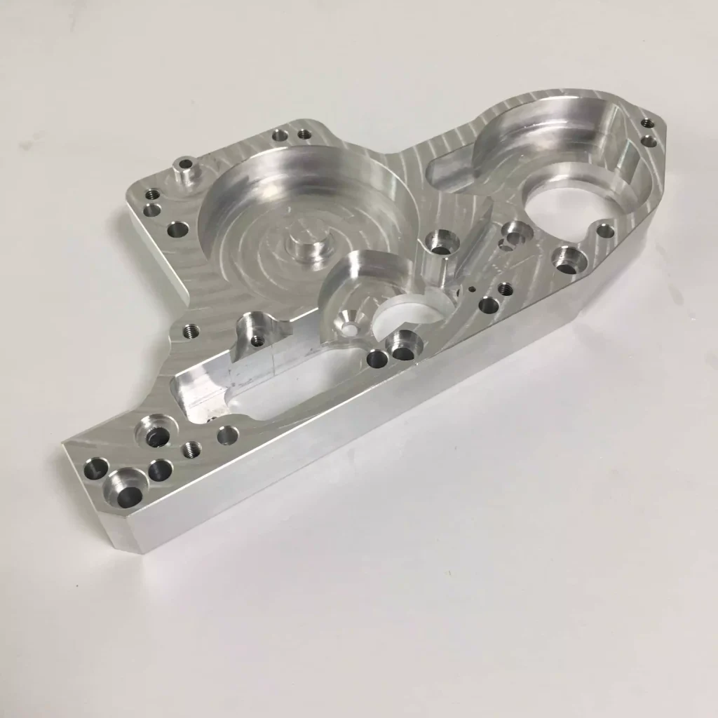
Traditional inspection methods remain widely used in CNC machining. Micrometers, bore gauges, calipers, and height gauges are practical tools for checking individual dimensions such as diameters, thicknesses, and distances between surfaces.
These tools are effective when the requirement focuses on a single measurement.
The limitation appears when several features must work together.
A CNC machined housing may include mounting holes, sealing surfaces, and alignment features. Each individual measurement can fall within tolerance, while the relationship between these features may still create an assembly issue.
For example, a hole with a diameter of Ø10 mm may be machined correctly within its size tolerance. However, the position of that hole relative to a datum surface may determine whether another component can be installed correctly.
The size of the hole is only one part of the requirement.
Engineering drawings often define how features relate to each other through datum references and geometric tolerances. The position of a hole pattern, the flatness of a mounting surface, or the alignment between two components can directly influence the function of the final assembly.
CMM inspection helps evaluate these relationships by measuring the part according to the coordinate system defined by the engineering drawing.
How CMM Inspection Works in CNC Machining
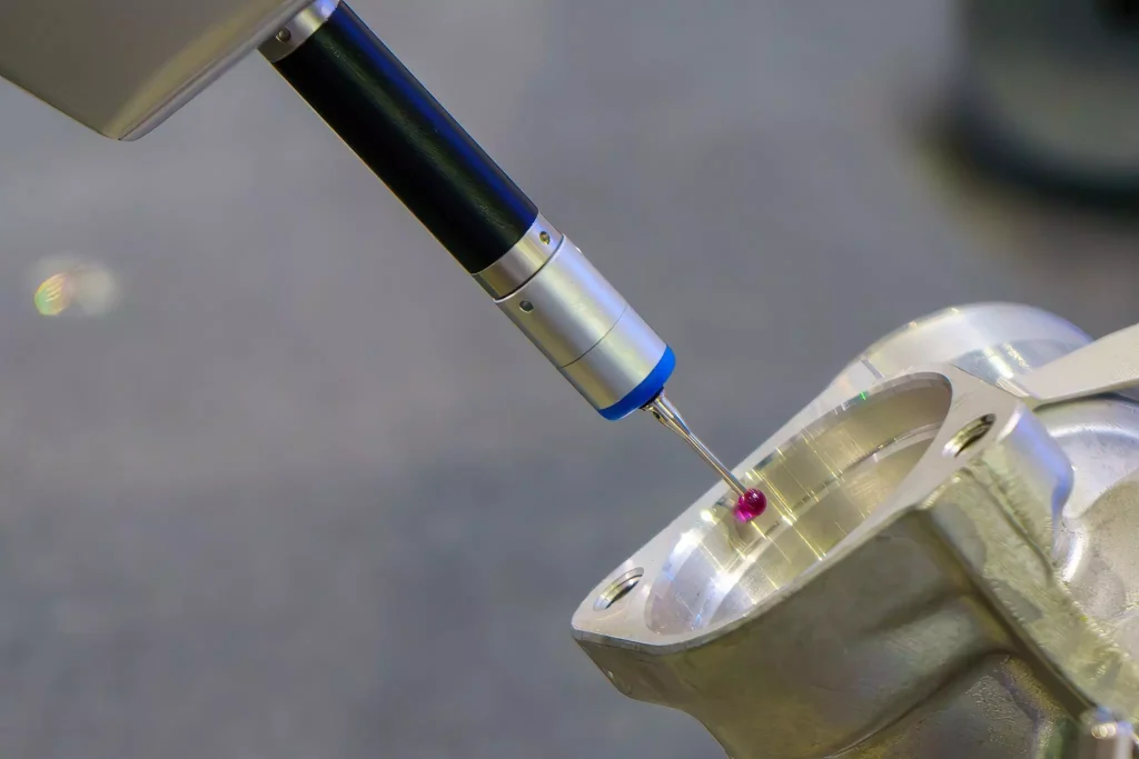
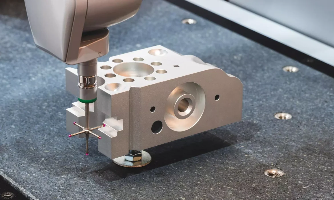
A Coordinate Measuring Machine measures the geometry of a machined component by collecting measurement points from selected surfaces and features through a probe system.
Before inspection begins, the part is positioned on the CMM table and aligned according to the datum references defined in the drawing.
Datums establish the reference system used for measurement. They are not simply measurement points. They represent the theoretical references from which other features are evaluated.
A drawing may define a machined surface as the primary datum and use holes or additional surfaces as secondary references. The CMM uses these references to recreate the same positional relationship used during the design process.
After the coordinate system is established, the probe measures the required features. The collected data is compared with the nominal geometry from the CAD model or engineering drawing.
The inspection result shows how the actual manufactured part differs from the intended design.
This process is particularly useful for CNC machined components where several features must maintain a controlled relationship. Instead of measuring each dimension separately, CMM inspection provides a complete view of the part geometry.
CMM Inspection and GD&T: Measuring Design Intent
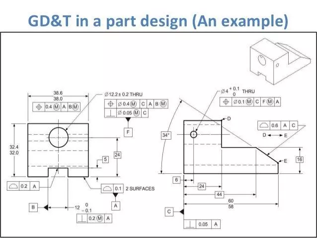
Many precision CNC machined parts use GD&T (Geometric Dimensioning and Tolerancing) because standard dimensional tolerances cannot fully describe functional requirements.
A basic dimension describes size.
GD&T describes how a feature should be positioned, oriented, or controlled relative to other features.
A hole provides a simple example.
A drawing may specify:
Hole diameter: Ø10 mm (10 mm diameter) with a tolerance of ±0.01 mm
This controls the size of the hole. The acceptable diameter range is from 9.99 mm to 10.01 mm.
The same drawing may also specify the position of that hole relative to defined datums. This controls where the hole must be located.
A hole can meet the diameter requirement and still be incorrectly positioned.
This difference matters in assemblies where components must align with each other. A clearance hole may allow more positional variation, while a locating hole used for assembly alignment may require tighter control.
CMM inspection is commonly used for GD&T verification because it measures features within the coordinate system established by the drawing. The result shows whether the actual feature location and geometry fall within the specified tolerance zone.
For engineers, this provides information closer to the functional requirement of the part rather than only confirming whether individual dimensions are within limits.
Understanding CMM Inspection Results
A CMM report provides measurement results based on the inspection requirements defined for the part.
The report typically compares the nominal value from the drawing with the actual measured value and shows the deviation.
For example, a hole position may have a nominal coordinate of 50.000 mm and an actual measurement of 50.006 mm, resulting in a deviation of +0.006 mm.
The deviation value itself does not determine whether the part is acceptable.
The engineering requirement and function of the feature must also be considered.
A 0.006 mm position deviation may have little impact on a non-critical clearance feature. The same deviation may affect assembly if the feature is used for precision alignment between components.
A useful CMM report helps engineers understand whether measured variation affects the intended application rather than only showing whether a number has changed from the nominal value.
How Accurate Is CMM Inspection?
CMM measurement capability depends on several factors, including machine specification, probe system, calibration condition, measurement strategy, and inspection environment.
Many precision bridge-type CMM systems used in manufacturing have measurement accuracy specified in the micron range. Depending on the machine class and operating conditions, some systems may have accuracy specifications around 1–3 μm plus a length-dependent factor under controlled conditions.
The actual inspection result also depends on environmental conditions, especially temperature.
Aluminum is one of the most common materials used in CNC machining because of its machinability and mechanical properties. Its thermal expansion coefficient is approximately 23.6 μm/m·°C.
For a 100 mm aluminum component, a temperature difference of 10°C can theoretically create dimensional variation of about 0.024 mm.
This effect becomes more noticeable when inspecting tighter tolerances. A feature produced within a few microns of the required value may be influenced by temperature differences between the part, measuring equipment, and inspection environment.
This does not mean every CNC inspection requires laboratory-level conditions. The inspection method should match the tolerance requirements and functional importance of the component.
CMM inspection does not improve machining accuracy by itself. It provides measurement information that helps manufacturers understand whether the machining process is producing parts within the required specifications.
CMM Inspection vs First Article Inspection (FAI)
CMM inspection and First Article Inspection (FAI) are often used together in CNC machining projects, but they serve different purposes.
CMM inspection is a measurement method. It collects dimensional and geometric data from a component and compares the results with engineering requirements.
FAI is a verification process used to confirm that the first production part meets the approved design specifications before regular production continues.
A first article inspection may include dimensional results, material information, surface finish verification, process documentation, and other requirements defined by the customer or industry standard.
CMM measurement is often one part of an FAI process when the component includes complex geometry or tight dimensional requirements.
For example, when producing a new CNC machined aluminum housing, the first article process may require verification of:
- Critical mounting locations
- Hole positions
- Surface dimensions
- Geometric tolerances
The CMM provides the measurement data needed to confirm these characteristics.
The distinction is useful because a CMM report alone does not represent a complete first article inspection. It provides measurement information, while FAI evaluates whether the entire manufacturing process has produced an acceptable first part.
CMM Inspection During Prototype and Production Machining
The role of CMM inspection changes depending on the production stage.
During prototyping, inspection is often focused on confirming whether the design can be manufactured as intended. A prototype may reveal issues related to machining access, tolerance requirements, assembly fit, or feature location.
CMM data helps identify these issues before moving into higher-volume production.
For example, a machined bracket may assemble correctly in the CAD model but show interference during physical assembly. A CMM report can help determine whether the issue comes from hole position, surface alignment, or another geometric variation.
During production machining, the focus shifts from initial verification to process consistency.
Repeated CMM measurements can show whether parts remain stable over time. Changes in feature position or dimensions may indicate tool wear, fixture movement, or changes in machining conditions.
The inspection approach depends on the manufacturing goal. Prototype inspection is often focused on understanding the part. Production inspection is often focused on maintaining consistent results.
Example: Why Feature Position Matters in CNC Machining
Consider a CNC machined aluminum housing used to hold another mechanical component.
The drawing specifies several mounting holes, a sealing surface, and alignment features. Each hole diameter is measured and found to be within tolerance.
From a basic dimensional inspection perspective, the part appears acceptable.
During assembly, however, the mating component does not align correctly.
The issue may not be the hole size. It may be that the hole pattern has shifted slightly relative to the reference surface.
A CMM inspection evaluates the position of the hole pattern based on the defined datums. The measurement data can show whether the holes are located within the required tolerance zone.
This example demonstrates why CNC inspection often focuses on relationships between features rather than only individual measurements.
When CMM Inspection Is Used for CNC Machined Parts
CMM inspection is generally considered when the function of a component depends on accurate feature relationships.
A simple machined spacer with basic dimensions may only require standard measurement methods. A precision fixture used to locate other components requires a different inspection approach because the position of each feature affects assembly repeatability.
The same applies to CNC machined housings, robotic components, aerospace parts, medical components, and industrial equipment parts where alignment and geometric accuracy influence final performance.
Components with complex geometry or multiple datum references are also more likely to require coordinate measurement because traditional inspection methods may not provide enough information.
The decision to use CMM inspection depends on the role of the component, the tolerance requirements, and the consequences of dimensional variation.
How CMM Data Helps Improve CNC Machining Processes
CMM inspection data can provide feedback beyond final part verification.
A single measurement outside tolerance does not always reveal the cause of a problem. Repeated measurement results can show patterns within the machining process.
A consistent shift in hole position across multiple parts may indicate fixture movement or setup variation.
A gradual change in diameter measurements may suggest tool wear.
Changes in surface profile may be related to machining parameters, cutting conditions, or material behavior.
Manufacturers can use this information to review machining conditions and make adjustments before producing additional parts.
For repeat production, inspection data provides a reference for monitoring process stability and identifying potential issues before they affect a larger batch of components.
CMM Inspection vs Traditional Measurement Methods
CMM inspection does not replace traditional measurement tools.
Each inspection method serves a different purpose.
Manual measurement tools are practical for checking individual dimensions during production. They are commonly used for features such as hole diameters, thicknesses, and simple distances.
CMM inspection becomes more useful when multiple features need to be evaluated within the same coordinate system.
A bore gauge can confirm the size of a hole. It cannot determine whether a group of holes maintains the correct relationship with a datum surface.
A height gauge can measure a distance between surfaces. It cannot provide the same level of geometric analysis required for complex GD&T requirements.
The appropriate inspection method depends on what the engineering requirement is controlling.
Working With CNC Machining Suppliers on Inspection Requirements
Inspection requirements should be discussed before machining begins.
Engineering drawings should clearly define critical dimensions, datum references, GD&T requirements, and any required inspection documentation.
Not every feature requires the same measurement approach. A practical inspection plan focuses on characteristics that influence assembly, performance, and product requirements.
When working with a CNC machining supplier, engineers should understand how inspection will be performed, including which features require CMM measurement, how the part will be aligned, and how results will be documented.
Clear communication between design and manufacturing teams helps ensure that inspection data reflects the actual engineering requirements.
A supplier’s inspection capability is not only about owning measurement equipment. The ability to interpret drawings, establish correct datum references, and provide meaningful measurement results is also important.
CMM Inspection at MS Machining
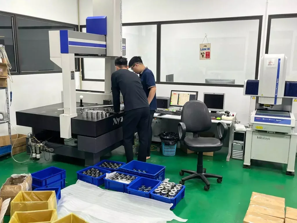
At MS Machining, inspection planning is considered together with part geometry, machining processes, tolerance requirements, and final application.
For CNC machined components where feature position, geometric relationships, or inspection documentation are important, CMM measurement provides detailed data for evaluating the finished part against engineering specifications.
The inspection approach is selected according to the requirements of each project rather than applying the same measurement method to every component.
Measurement results are used as part of the manufacturing process to help evaluate whether the finished component matches the defined requirements.
Conclusion
CMM inspection plays an important role in CNC machining when part performance depends on more than individual dimensions.
The purpose of CMM measurement is not simply to generate an inspection report. It provides a method to evaluate whether the manufactured component maintains the geometry, alignment, and feature relationships required by the original design.
For engineers, understanding CMM inspection helps define practical manufacturing requirements, communicate more effectively with CNC machining suppliers, and make decisions based on measurement data rather than assumptions.
A suitable inspection approach connects engineering requirements with actual manufacturing results, creating a clearer path from design intent to finished component.
FAQ
What is CMM inspection in CNC machining?
CMM inspection is a measurement process that uses a coordinate measuring machine to evaluate the dimensions, geometry, and feature relationships of CNC machined parts.
Why is CMM inspection used for precision CNC parts?
CMM inspection is used when part function depends on feature position, geometric tolerances, or alignment between multiple components.
Can CMM measure GD&T requirements?
Yes. CMM systems are commonly used to evaluate GD&T requirements such as position, flatness, alignment, and geometric relationships between features.
Does CMM inspection replace manual measurement?
No. Manual measurement tools and CMM inspection are used for different purposes depending on the inspection requirement.
Does every CNC machined part need a CMM report?
No. The need for CMM inspection depends on part complexity, tolerance requirements, application, and customer documentation requirements.