
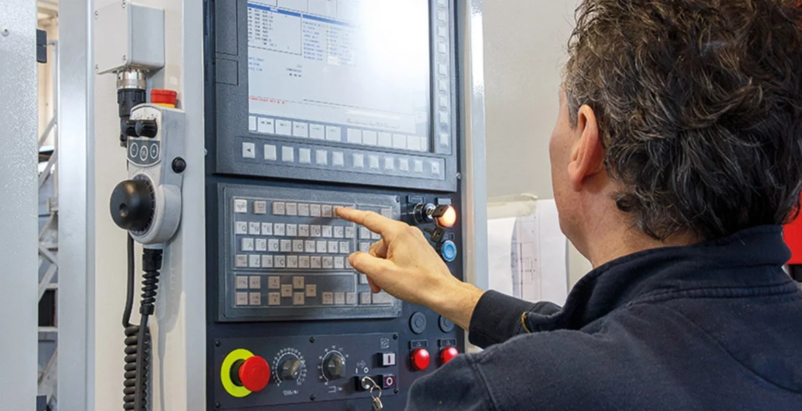
When a CNC machined part fails to meet the drawing requirements, the problem is not always caused by programming mistakes or incorrect dimensions in the design file. In many cases, the actual cause comes from the machine itself — how accurately it positions the tool, how stable the spindle runs, how well the structure resists cutting forces, and how the system manages heat during machining.
A CNC machine is a combination of mechanical, electrical, and control systems working together. The controller provides instructions, the motion system moves the cutting tool, the spindle generates cutting movement, and the machine structure maintains stability throughout the process.
For simple parts, the influence of each component may not be obvious. However, when machining precision components with tight tolerances, complex geometries, thin walls, or difficult materials, the performance of each system directly affects the final result.
Understanding CNC machine components is not only about identifying the parts inside the equipment. It is about understanding why a machine can consistently produce accurate parts and why different machines or suppliers may achieve different machining results from the same drawing.
Learn more:What Are Precision CNC Machining Services and How Do They Work?
Machine Structure: The Foundation That Determines Machining Stability
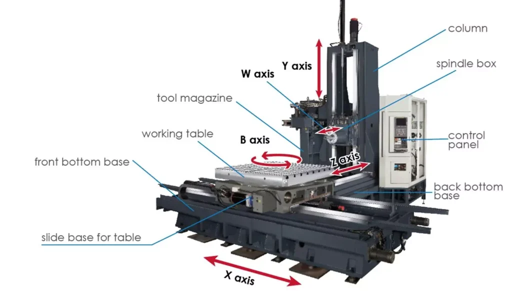
The machine structure provides the physical foundation for all machining operations. The bed, column, table, and spindle housing work together to maintain the relative position between the cutting tool and the workpiece.
During cutting, the tool does not simply remove material without resistance. The workpiece pushes back against the tool, creating cutting forces that travel through the tool holder, spindle, and machine frame. If the structure lacks rigidity, these forces can cause vibration or small deflections during machining.
This becomes more noticeable when machining parts with challenging features. Thin-wall components can deform under cutting pressure, deep cavities can create vibration due to long tool overhangs, and hard materials such as stainless steel or titanium alloys generate higher cutting loads compared with aluminum.
For example, when finishing a precision mounting surface, even small vibrations can leave visible tool marks or create dimensional variation. The machine may still follow the programmed path, but the actual cutting condition has changed because the structure is moving under load.
This is why machine rigidity is not only about supporting the weight of the equipment. It determines how consistently the machine can maintain accuracy while cutting real materials under real production conditions.
Motion System: How CNC Machines Maintain Position Accuracy
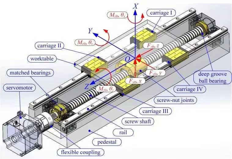
The motion system is responsible for moving the cutting tool according to programmed coordinates. It includes servo motors, ball screws, linear guides, and position feedback systems.
In precision machining, movement accuracy is not only about reaching a specific position once. The machine must repeatedly return to the same position during hundreds or thousands of machining cycles.
One common factor affecting accuracy is backlash. When the axis changes direction, any clearance in the transmission system can create a small delay between the commanded movement and the actual movement. This error may seem minor, but it can affect features that require accurate positioning, such as multiple holes, mating surfaces, or alignment features.
The feedback system helps compensate for movement errors by continuously monitoring axis position. However, the mechanical condition of the components still matters. Wear in guideways, reduced ball screw accuracy, or poor calibration can gradually affect repeatability.
For CNC machining services, motion system performance directly influences whether a supplier can maintain consistent tolerances across prototype parts and production quantities.
Spindle System: The Component That Controls Cutting Performance
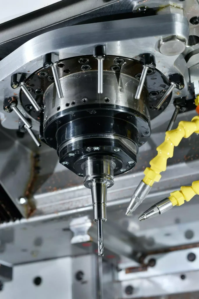
The spindle is responsible for rotating the cutting tool, but its role goes far beyond providing rotational speed. The stability and accuracy of the spindle directly affect how the tool interacts with the material.
A spindle with excessive runout can cause the cutting edge to move away from the intended cutting path. During operations such as precision boring or finishing passes, this can influence hole diameter, roundness, and surface finish.
Spindle bearings and thermal stability also play an important role. During long machining cycles, heat generated by high-speed rotation can cause small changes in spindle position. These changes may become noticeable when producing parts that require consistent dimensions over extended production runs.
Spindle power and torque also need to match the material being machined. Aluminum machining often benefits from higher spindle speeds, while materials such as stainless steel, titanium, and nickel alloys require stable cutting forces to prevent excessive tool wear and vibration.
A capable spindle allows the cutting tool to maintain stable performance across different machining conditions.
CNC Controller: Turning Digital Instructions Into Accurate Movements
The CNC controller acts as the communication center between the machining program and the physical machine. It interprets G-code instructions and coordinates axis movement, spindle speed, and machining operations.
For basic three-axis machining, the controller manages linear movements along the X, Y, and Z axes. However, complex components often require more advanced control.
In five-axis machining, the controller must coordinate linear and rotary movements simultaneously. The cutting tool may need to change orientation while moving along the workpiece surface to maintain the correct cutting angle.
This capability is important for aerospace components, medical parts, and complex industrial components where multiple surfaces or curved geometries need to be machined accurately.
The difference between basic and advanced CNC control is not simply the number of available axes. It is the ability to maintain accurate coordination between different movements while the machine is cutting.
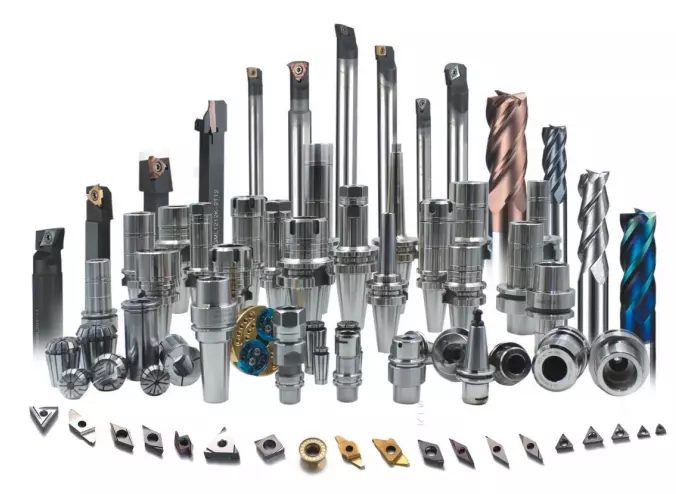
Tooling System: The Link Between Machine Capability and Cutting Results
Even a highly accurate CNC machine cannot produce good parts without the right tooling system.
The cutting tool directly determines how material is removed. Tool material, geometry, coating, diameter, and cutting parameters all influence machining performance.
Tool deflection is a common challenge when machining deep pockets or narrow features. A longer tool extension provides access to difficult areas but reduces rigidity. Under cutting forces, the tool may bend slightly, affecting dimensional accuracy and surface finish.
Tool holders also influence stability. Poor clamping conditions can introduce vibration and reduce the effectiveness of the spindle’s accuracy.
For precision CNC machining, tool selection is not separated from machine capability. The machine, spindle, tool holder, and cutting tool must work together as one system.
Workholding System: Keeping the Part Stable During Machining
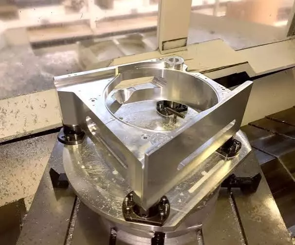
The workholding system is often overlooked, but it plays a critical role in machining accuracy.
A CNC machine may position the tool accurately, but the result will still be affected if the workpiece moves during cutting. Fixtures and clamps need to hold the part securely while avoiding unnecessary deformation.
This is especially important for thin aluminum components, precision brackets, and parts with uneven wall thickness. Excessive clamping force can distort the part before machining even begins, while insufficient holding force can allow movement during cutting.
Proper workholding design considers the material, geometry, cutting direction, and machining sequence. A stable fixture helps the machine achieve the accuracy that the program was designed to deliver.
Cooling and Chip Management: Maintaining Consistent Machining Conditions
Machining is not only a mechanical process; it is also a thermal process.
Cutting generates heat at the contact area between the tool and workpiece. If this heat is not controlled, tool wear increases and the dimensions of the part may change during longer machining cycles.
Coolant systems help manage cutting temperature and improve chip removal. This becomes particularly important when machining materials with poor thermal conductivity, such as titanium alloys.
Chip management is another factor affecting stability. If chips accumulate around the cutting area, they can interfere with the tool path, damage the surface finish, or cause unstable cutting conditions.
In production machining, maintaining a consistent environment is essential because small variations repeated over many parts can lead to quality issues.
Why Different CNC Machines Produce Different Results From the Same Drawing
A CNC machine’s specifications do not tell the entire story. Two machines may have similar spindle speeds, travels, and control systems but still produce different results.
The difference often comes from the condition of the equipment, calibration accuracy, tooling choices, fixture design, machining strategy, and operator experience.
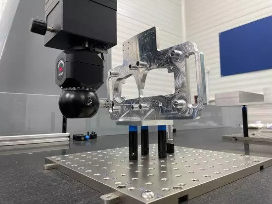
A precision component requires more than a machine capable of reaching a certain tolerance. The machining process must control every factor that influences the final result, from tool selection to cutting parameters and inspection methods.
This is why experienced CNC machining suppliers focus not only on equipment investment but also on process control and manufacturing knowledge.
CNC Milling and CNC Turning: Different Machines for Different Applications
CNC milling machines and CNC turning machines use different approaches to remove material.
In CNC milling, the cutting tool rotates while the workpiece remains fixed. This allows the machine to create complex shapes, pockets, slots, holes, and multi-sided features.
In CNC turning, the workpiece rotates while the cutting tool removes material along the surface. This process is commonly used for shafts, bushings, and cylindrical components.
Many industrial parts require a combination of machining methods. The best approach depends on the geometry, material, tolerance requirements, and production volume of the component.
Conclusion
A CNC machine is not defined by one single component. Its machining performance comes from the interaction between structural rigidity, motion accuracy, spindle stability, control capability, tooling, workholding, and thermal management.
Each system affects a different part of the machining process. The structure resists cutting forces, the motion system controls positioning, the spindle maintains cutting conditions, and the control system coordinates every movement.
For companies looking for CNC machining services, evaluating manufacturing capability requires more than checking machine models. Consistent part quality comes from the combination of suitable equipment, proper machining processes, and practical experience in controlling the factors that affect precision.