
When precision, structural integrity, and repeatable performance are required, billet machining becomes one of the most reliable manufacturing approaches in modern engineering production. From aerospace brackets and robotics components to hydraulic manifolds and semiconductor fixtures, this process is widely used when part failure is not an option.
Unlike forming processes such as casting or forging, billet machining builds the final geometry directly from a solid block of material, allowing engineers to control dimensional accuracy, surface quality, and internal consistency with far greater predictability.
1. What Is Billet Machining?
Billet machining is a subtractive manufacturing process that creates a finished component by systematically removing material from a solid metal block using advanced CNC milling, turning, drilling, and multi-axis machining operations.
A “billet” is not an alloy grade, but a raw material format—typically a solid, dense, and homogeneous block of metal produced through continuous casting and then heavily refined through mechanical deformation processes such as hot rolling or extrusion.
Unlike casting, where molten metal solidifies into a shape, or forging, where material is plastically deformed under massive pressure, billet machining starts with fully dense wrought stock and subtracts material until the final geometry is achieved. This makes it the industry benchmark for components that require tight tolerances, predictable mechanical behavior, and high-quality surface finishes.
2. How the Billet Machining Process Works
Executing a high-tolerance billet component requires a synchronized CNC workflow where software programming and machine physics align perfectly.
- Step 1 – Material Selection & Microstructural Verification: Select the alloy based on mechanical loads and environment. Engineers must verify the material’s temper (e.g., T6 for aluminum) and secure traceability documents to ensure zero internal structural anomalies before machining begins.
- Step 2 – Billet Preparation & Sizing: Raw bar or plate stock is sawn into optimized blanks. On the shop floor, strategic sizing is critical: leaving too much stock increases cycle times and tool wear, while leaving too little compromises clamping stability and fixture rigidity.
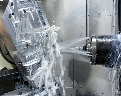
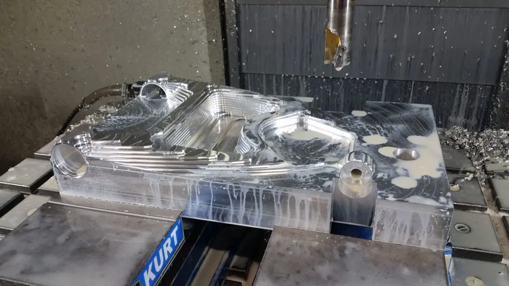
- Step 3 – Multi-Axis CNC Machining: The blank is shaped using CAM-programmed toolpaths on 3-axis, 4-axis, or 5-axis machining centers. High-speed milling, pocketing, and contouring execute the geometry. For complex parts, 5-axis simultaneous machining is utilized to cut multi-angled features in a single setup, eliminating stacking errors caused by manual repositioning.
- Step 4 – Controlled Surface Finishing: The machined part undergoes post-processing to modify its surface profile. This includes bead blasting to uniformize tool marks, chemical passivation for stainless steel, or anodizing for aluminum parts to enhance corrosion and wear resistance.
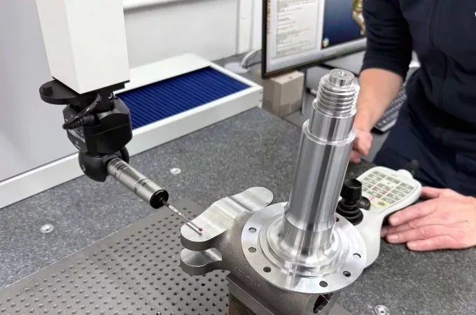
- Step 5 – Metrology & Quality Assurance: Dimensions are validated against the engineering print using automated Coordinate Measuring Machines (CMM), calibrated thread Go/No-Go gauges, and digital profilometers to check surface roughness ($R_a$).
3. The Materials Science Behind Billet Machining
The true performance advantages of billet machining are deep-seated in metallurgy.
Grain Structure and Material Stability
Because billet stock is produced via extrusion or rolling, its internal crystalline grain structure is elongated and compressed along a definitive axis. This creates predictable, highly stable mechanical properties.
During machining, this uniform matrix yields exceptional benefits:
- Consistent resistance against the cutting edge.
- Predictable, clean chip formation that avoids chip nesting around the spindle.
- Highly controllable surface finishes across the entire batch.
Shop-Floor Insight on Structural Stress: Even high-grade billet material contains internal residual stresses from the mill’s quenching process. When you execute heavy roughing to hollow out large pockets, this equilibrium is disrupted, causing the part to warp or “spring back.” To counteract this dynamic behavior, experienced machinists use a staged strategy: rough out the bulk material, unclamp the part to allow the internal stresses to relax, re-clamp with minimal force, and then run light finish toolpaths to lock in the final dimensions.
Billet vs. Casting: Internal Defect Risk
Liquid metal forming processes (casting) are inherently vulnerable to solidification physics. As the melt cools, gas becomes trapped, and volume contraction occurs, leading to gas porosity and shrinkage cavities.
Under cyclic, high-pressure, or structural loading, these hidden sub-surface voids act as stress-concentration nodes where micro-cracks initiate and propagate, causing catastrophic fatigue failure. Billet machining completely bypasses this risk by utilizing 100% dense, wrought material, removing porosity from the failure equation.
4. Billet Machining vs. Casting vs. Forging
| Engineering Feature | Billet CNC Machining | Metal Die Casting | Industrial Forging |
| Internal Porosity Risk | None (100% Dense Wrought Matrix) | High (Gas & Shrinkage Voids) | None (Highly Compressed) |
| Achievable Tolerances | ±0.005 mm (Micron-level) | ±0.2 mm to ±0.5 mm | ±0.3 mm to ±0.8 mm |
| Upfront Tooling Cost | $0 (Zero Tooling Capital) | High ($15,000 – $50,000+) | Very High ($20,000 – $80,000+) |
| Design Revision Agility | Instant (Via CAM/G-code updates) | Prohibitive (Requires tool mod) | Impossible (Requires new dies) |
| Surface Finish (Ra) | Excellent (0.8 μm or better) | Fair (3.2 μm – 6.3 μm) | Fair (3.2 μm – 12.5 μm) |
When Billet Machining Is the Better Choice
Billet machining is mathematically and operationally preferred when parts demand sub-micron accuracy, when design iterations are frequent during prototyping, or when production volumes sit between 1 and 1,000 units, making hard tooling amortization uneconomical.
Tool Life Alert on Cast Blanks: In hybrid setups where castings are post-machined, the raw casting’s outer skin is highly abrasive and rich in oxides. If a CNC toolpath barely grazes this outer crust, the carbide insert will experience immediate micro-chipping. Machinists must ensure the first roughing cut plunges deep below the casting skin to safeguard tool life and maintain batch tolerance stability.
5. Precision Boundaries: Tolerances and Surface Finish
Billet CNC machining operates in a precision echelon that near-net-shape forming processes cannot reach.
- Standard Machining Features: ±0.05 mm — suitable for general clearance fits and non-mating structural faces.
- Precision Engineered Features: ±0.01 mm — used for alignment pins and standard press-fits.
- High-Precision Applications: ±0.005 mm — mandatory for high-RPM bearing journals, semiconductor positioning matrices, and critical O-ring sealing grooves.
Surface Roughness (Ra) and Edge Integrity: What It Means for Your Assembly
While cast parts leave a rough, pitted finish (Ra 3.2 – 6.3 μm), billet machining consistently hits Ra 0.8 μm or better natively off the machine. To put this into perspective for real-world engineering applications:
- Zero Leakage at Sealing Interfaces: For hydraulic manifolds or vacuum valves, a rough cast surface acts as a microscopic network of leak paths. An Ra 0.8 μm billet finish provides a flawless, mirror-like mating surface that ensures O-rings and gaskets compress uniformly, completely eliminating fluid or gas pressure drops.
- Reduced Wear on Bearing & Moving Parts: In robotics and automotive performance components, running moving parts against a rough cast finish creates massive friction, rapid heat generation, and premature wear. Billet machining drastically lowers the friction coefficient, extending the service life of dynamic seals, bearings, and shafts.
- Flawless Surface Aesthetics and Edge Control: In high-end aesthetic parts, the raw material’s temper directly dictates the edge quality. When machining fully aged 6061-T6 aluminum, the metal shears cleanly under the tool, leaving crisp, burr-free chamfers. However, softer casting alloys tend to be “gummy.” During cutting, this gummy metal adheres to the cutter edge and creates a Built-Up Edge (BUE). This results in microscopic burrs and ragged edges that fail cosmetic inspections and cause uneven dye accumulation during the anodizing process.
6. Common Materials Used in Billet Machining
Material selection directly dictates machinability, cutting forces, and post-processing outcomes.
- 6061-T6 Aluminum: The backbone of general engineering. Offers excellent strength-to-weight ratio, high machinability, and responds perfectly to anodizing for a uniform, vibrant, and corrosion-resistant finish.
- 7075-T6 Aluminum: Aerospace-grade alloy. Possesses copper additions that elevate its yield strength to rival structural steel, though it requires precise tool geometries to manage higher cutting forces and thermal loads.
- Stainless Steel 304 / 316: Selected for industrial, chemical, and marine applications. 316 contains Molybdenum, providing elite resistance to pitting corrosion in chloride environments. Both work-harden rapidly, requiring rigid setups and sharp cutting edges.
- Titanium Grade 5 (Ti-6Al-4V): Biocompatible and highly resilient, dominating aerospace UAVs and medical implants. Its low thermal conductivity locks heat at the cutting zone, requiring precise coolant delivery (often through-spindle) to prevent rapid tool breakdown.
- Brass: Excellent electrical conductivity and low friction coefficient. Extremely easy to machine at high feed rates without accelerating tool wear.
7. Typical Applications of Billet Machining
- Aerospace Structures: UAV links, bulkhead segments, and avionic enclosures where weight minimization and zero internal material defects are non-negotiable.
- Robotics & Automation: Precision articulating joints, structural arm segments, and gripper bases that require low mass paired with absolute dimensional repeatability.
- Semiconductor Equipment: Vacuum chamber fixtures, wafer-handling arms, and matrix alignment plates requiring ultra-tight tolerances and zero-outgassing surfaces.
- Medical Instrumentation: Orthopedic surgical guides, imaging system housings, and internal implantable structures.
- Hydraulic and Fluid Systems: High-pressure manifolds machined from solid block to eliminate leak paths and handle extreme hydraulic cyclic loading.
8. Total Cost of Ownership (TCO)
A frequent procurement error is evaluating manufacturing costs solely based on the material utilization rate (the volume of chip scrap generated during the cutting process). A comprehensive lifecycle financial analysis reveals that billet machining often delivers a significantly lower Total Cost of Ownership when evaluating the entire product span.
When calculating the true economic impact of a project, procurement teams must look beyond the per-unit piece price and factor in the following cost drivers:
- Upfront Tooling Capital: Casting and forging require massive initial expenditures for engineering, sinking, and testing steel molds or dies (often running from $15,000 to $80,000+). Billet machining requires zero tooling investment. Production begins immediately once the 3D CAD model is converted into optimized CNC toolpaths.
- Production Lead Time & Speed to Market: Waiting 6 to 12 weeks for hard tooling to be fabricated freezes your capital and delays revenue. Billet machining offers instantaneous setup, turning raw stock into production-ready parts within 24 to 48 hours.
- Design Revision Agility: If a field failure occurs or an R&D engineer optimizes a feature mid-production, adapting a billet component requires nothing more than updating a line of code in the CAM software. If that same modification is needed on a cast component, the steel mold must be welded, machined down, or completely scrapped—causing catastrophic supply chain bottlenecks.
- Risk Mitigation (Scrap & Down-Time): Factoring in the cost of unexpected field failures caused by hidden casting porosity or structural thread stripping quickly shifts the financial advantage back to the guaranteed, 100% dense matrix of billet parts.
9. Quality Assurance Checklist
To ensure production consistency and protect critical assembly lines from non-conforming components, technical buyers should mandate that their billet machining partner provide the following quality verification package:
- Mill Test Report (MTR): Certifies chemical composition and mechanical properties back to the original heat lot, ensuring the material is genuine and compliant with ASTM/ISO standards.
- CMM Dimensional Report: Provides digital, objective verification of all high-precision geometries and geometric tolerances (GD&T).
- Thread Go/No-Go Gauge Certification: Ensures all internal tapped holes conform to class fits, mitigating the risk of thread stripping or loose assemblies under vibration.
- Surface Roughness Verification: Profilometer data confirming compliance with specified Ra metrics on functional faces.
10. FAQ About Billet Machining
Is billet machining stronger than casting?
Yes. Billet materials are produced from wrought stock that has undergone mechanical rolling or extrusion, which closes micro-voids, eliminates gas porosity, and refines grain structure. Castings are fundamentally prone to internal porosity and cooling defects that lower fatigue limits.
Is billet machining stronger than forging?
Not inherently. Forging deforms metal along the natural contoured shape of the part, providing highly optimized directional grain flow for extreme impact resistance. However, forgings lack precision and almost always require secondary billet-style CNC machining to achieve functional tolerances and mating surfaces.
Why is billet machining considered premium?
Because it involves subtracting material from a solid block, resulting in higher material waste and longer cycle times compared to casting a raw shape. However, it completely eliminates upfront tooling costs and allows for immediate engineering flexibility.
What materials are commonly used?
Aluminum (6061, 7075), stainless steel (304, 316), titanium (Grade 5), and brass are the most common billet machining materials.
What industries use billet machined parts?
Aerospace, robotics, semiconductor, medical, automotive performance, and oil & gas industries.
Conclusion
Selecting billet machining isn’t just a material format decision; it’s a strategic move to lock in absolute material integrity, micron-level accuracy, and superior surface aesthetics. When your application cannot tolerate micro-porosity, part distortion, or loose tolerances, billet CNC machining stands as the ultimate manufacturing standard.
At MS Machining, we don’t just execute toolpaths—we function as your technical engineering partner. Our facility specializes in precision multi-axis CNC milling, turning, and complete contract manufacturing for high-consequence industries.


