

CNC machining milling services are defined by strict physical realities on the shop floor. Step inside any high-tier production facility, and the environment speaks a distinct language. It is the rhythmic, low-frequency hum of a heavy cast-iron chassis stabilizing a massive cutting load. It is the sharp whistle of a solid carbide end mill spinning at 12,000 RPM, shearing through solid block metal. It is the violent hiss of high-pressure synthetic coolant vaporizing into a white mist as it hits the shearing zone, evacuating silver, razor-sharp chips into the chip conveyor enclosure.
For procurement managers and hardware engineers sourcing external manufacturing partners, the quoting stage often feels like a black box. You upload a finalized STEP file to three premium suppliers, and the cost estimates come back with a 200% variance. One shop flags your tighter tolerances as a production bottleneck, while another quotes an exorbitant setup fee without explaining the underlying engineering logic.
The hidden friction in contract manufacturing is rarely about raw material costs; it is about how a digital file translates to the mechanical physics of the shop floor. When a part features micro-chatter marks, distorted thread profiles, or dimensions that bind during final assembly, it is usually because the 3D model forced the machinery into an unstable state. To bridge this structural gap and control your unit margins, this guide bypasses generic marketing promises. Instead, we analyze the mechanical constraints of the machine shop floor, allowing your team to design out manufacturing premiums before a tool ever touches raw stock.
1. Kinetic Axes & Machine Selection: Matching Your Geometry to the Right Spindle Architecture
A common procurement error is paying for excessive machine capability, or conversely, forcing a highly complex geometry onto rigid, low-axis machinery, which drives up manual labor costs. To optimize your piece-part pricing, you must understand exactly how a spindle moves relative to your workpiece.
       [Vertical Spindle]               [Horizontal Spindle]
               |                                 ___
               v                                |   |===> (Spindle)
         +-----------+                           ---
         | Workpiece |                      +-----------+
         +-----------+                      | Workpiece |
       [VMC Architecture]                   +-----------+
                                         [HMC Architecture]
3-Axis Machining and the Economics of Vertical Processing (VMC)
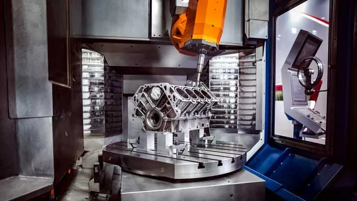
The standard workhorse of the modern shop floor is the Vertical Machining Center (VMC). In a VMC configuration, the raw material block is clamped flat to a rigid mechanical vise on the worktable. The spindle axis is oriented vertically, approaching the workpiece from above and moving along the X, Y, and Z Cartesian axes.
From a cost perspective, 3-axis VMC processing offers the lowest hourly machine rate. The setups are straightforward, the fixturing is highly standardized, and the machine structure provides exceptional downward gravitational rigidity, making it ideal for aggressive mass excavation of material (roughing). If your component consists of flat mounting plates, simple brackets, top-down pockets, or planar profiling, it belongs on a VMC. Designing a part that can be completed entirely from a single top-down orientation ensures you are not paying an unnecessary premium for advanced multi-axis motion. This structural baseline represents the most cost-effective tier of standard cnc machining vs milling classification.
Horizontal Machining (HMC): Chip Control and High-Volume Efficiency
When a component transitions from a flat bracket to a multi-sided industrial enclosure, box-shaped valve body, or transmission housing, processing on a vertical machine becomes highly inefficient. This is where the Horizontal Machining Center (HMC) becomes essential.
In an HMC, the spindle is mounted horizontally, approaching the material from the side. The workpiece is typically mounted to a vertical column called a “tombstone,” which sits on a rotating indexing pallet or NC rotary table.
               +---+
               |   | <--- Horizontal Spindle
       +-------+---+-------+
       |     Tombstone     |  <--- Rotates on B-Axis
       +-------+---+-------+
               |   |
For an engineer, the HMC provides two massive physical advantages:
- Gravity-Assisted Chip Evacuation: In a deep vertical pocket on a VMC, chips tend to settle at the bottom of the cavity. The cutter must repeatedly slice through its own debris (re-cutting), which accelerates tool wear and leaves micro-scratches on the interior walls. On an HMC, the chips drop naturally away from the cutting zone under their own weight, preserving tool life and interior surface finish.
- Multi-Face Processing via Indexing: The rotating tombstone allows the cutting tool to access four distinct faces of a component in a single mechanical setup. By minimizing the human intervention required to manually unclamp, flip, and re-clamp a part, an HMC dramatically slashes labor costs and eliminates human alignment errors across mid-to-high volume production runs.
5-Axis CNC Machining: Eliminating Tolerance Accumulation Through One-Step Setup
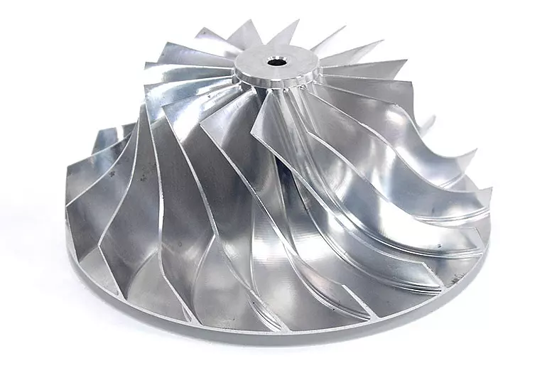
For aerospace impellers, complex medical orthopedic implants, or organic, highly contoured geometries, traditional 3-axis boundaries fail. These components require 5-axis CNC machining. This architecture adds two rotational movements (typically an A-axis rotating around the X-axis, and a C-axis rotating around the Z-axis), allowing the machine spindle to approach the raw material from any vector in a 3D hemisphere.
                   Z
                   |   Y
                   |  /
                   | /
                   +------- X
                  / \
                 A   C  <--- Rotational Axes
A common misconception is that five-axis capabilities are reserved exclusively for complex, futuristic curves. In reality, experienced production engineers leverage five-axis machinery for flat, multi-angled prismatic parts to exploit the “Single-Setup” rule. Every time a human operator manually relocates a part from one vise to another across multiple machine setups, a minor positioning error is introduced. Even with precision ground locating pins, a variance of ±0.02 mm can easily slip into the setup. If a part requires four separate adjustments, these errors accumulate, pushing critical coaxial holes or perpendicular faces out of alignment.
Five-axis processing eliminates manual relocation. The machine grips the raw stock once, and the rotary axes position the part continuously against the tool face. You are not just buying geometric complexity; you are investing in mechanical registration to guarantee absolute geometric trueness across multiple faces.
The Realities of Setup Fees and Fixturing Costs
When reviewing a low-volume prototyping quote, customers often wonder why five components cost $300 each, while a run of five hundred drops the cost to $25 each. The variance lies in the non-recurring engineering (NRE) time and physical workholding creation.
Before a single chip is cut, a CNC programmer must map out toolpaths, calculate feed rates, set coordinate systems, and physically build the workholding system. If your part features highly complex, irregular geometries with no flat parallel faces, the machinist cannot simply drop it into a standard vise. They must design and machine custom “soft jaws”—aluminum vise inserts milled to mirror the exact contours of your unique part.
Standard Vise Jaws:        Custom Soft Jaws:
   +---+      +---+           +---+      +---+
   |   |      |   |           |   |__  __|   |  <-- Mirrored profile
   |   | Part |   |           |   |  \/  |   |     of your irregular part
   +---+      +---+           +---+      +---+
For a prototype run of three units, the cost of designing, testing, and machining those soft jaws is distributed across just three parts. To optimize your early-stage budget, always aim to incorporate flat, parallel clamping features into your initial designs, allowing the shop floor to secure the raw stock using standard off-the-shelf workholding.
2. Managing Precision: The Interdependence of Tolerances, Surface Finish, and Heat
In precision manufacturing, requesting extreme accuracy on a drawing without understanding its mechanical and thermal consequences is the fastest way to balloon your project budget. Every extra decimal place added to a dimension completely alters how that part must be physically managed on the shop floor.
The Exponential Cost Scale of Tolerances
A standard, commercially viable milling tolerance is ±0.1 mm for non-critical features, and ±0.02 mm for standard mating alignments. At these tiers, a standard machine can run at peak speeds, utilizing standard workholding and standard cutting tools.
Cost |
| * (±0.005mm)
| *
| *
| * (±0.02mm)
| * (±0.1mm)
+----------------------------------------
Tolerance Strictness
The moment a drawing demands a micro-precision tolerance of ±0.005 mm, the manufacturing approach shifts entirely:
- Tooling Transformation: Standard carbide end mills are no longer sufficient; the shop must deploy premium, high-tier micro-grain cutting tools with minimal radial runout.
- Cycle Time Expansion: The machine cannot perform aggressive, rapid cuts. It must execute multiple micro-stepped finish passes, significantly extending the cycle time.
- Metrology & Inspection Escalation: The part cannot be validated using basic digital calipers or micrometers at the machine box. It must be transferred to a dedicated Quality Assurance lab, sitting in a climate-controlled environment to stabilize its temperature before validation on a coordinate measuring machine (CMM).
| Fit Type | Recommended Tolerance | Typical Application | Cost Impact |
|---|---|---|---|
| Free Profile / Housing | ±0.1 mm | Enclosures, non-mating faces | Baseline cost, rapid machining |
| Standard Alignment Fit | ±0.02 mm | Bearing blocks, locating pin holes | Moderate cost, secondary finish pass |
| Micro-Precision Match | ±0.005 mm | Hydraulic spools, optical alignments | Extreme cost, requires temperature tracking |
The Physical Nature of Surface Finish (Ra)
Surface finish, expressed as Roughness Average (Ra), is a direct trace of the cutting tool’s path through the material. It represents the microscopic peaks and valleys left behind by the rounded tip (nose radius) of a milling cutter as it steps across the face of the metal.
Cutter Profile:       \_______/   \_______/
                             ^           ^
Microscopic View:     _______/ \________/ \_______
                             <---------->
                              Scallop Width (Stepover)
An unrefined roughing pass typically yields an Ra 3.2 μm finish. The tool marks are highly visible to the naked eye and easily felt with a fingernail. While perfectly acceptable for internal structural frames or basic clearance brackets, it is completely unsuitable for dynamic, sliding fluid seals or high-stress aerospace components prone to fatigue cracking.
To refine the finish to a smooth Ra 1.6 μm or a pristine Ra 0.4 μm, the programmer must adjust two primary variables: tool feed rate and stepover distance (the lateral distance the tool moves between parallel passes). To achieve an ultra-smooth surface directly off the machine spindle, the stepover must be compressed to a fraction of a millimeter, forcing the tool to take thousands of dense, overlapping micro-passes. A face that takes 45 seconds to rough out at Ra 3.2 μm can easily take 20 minutes to finish to an Ra 0.4 μm spec. Unless your component relies on a high-precision metal-to-metal sealing interface or high-frequency dynamic loading, leaving surfaces at Ra 1.6 μm or Ra 3.2 μm keeps your cycle costs low.
The Post-Processing Dimension Gap
A frequent source of frustration occurs when a customer inspects an anodized aluminum component and finds that a high-precision press-fit bearing bore is suddenly out of specification. The culprit is a failure to account for the physical thickness of post-processing coatings during the initial design phase.
Before Anodizing (Milled Spec):   After Hard Anodizing:
      |   ---  50.00 mm  ---   |          |   ---  49.96 mm  ---   |
      +--------------------+          +====================+
      |      Aluminum      |          | Oxide | Aluminum |Oxide|
      +--------------------+          +====================+
                                              ^          ^
                                       Coating penetrates & builds up
Type II decorative anodizing typically adds a surface layer of 5 μm to 15 μm per side. Type III Hardcoat Anodizing, engineered for heavy industrial wear and corrosion resistance, deposits a thick, dense oxide layer ranging from 25 μm to 50 μm per side. Crucially, an anodizing layer grows outwards while simultaneously penetrating inward into the base aluminum substrate. If your drawing demands a strict pin-clearance hole of 10.00 mm ±0.01 mm, and the shop machines the raw aluminum to exactly 10.00 mm, a subsequent Type III Hardcoat step will constrict that hole diameter by up to 0.05 mm, ruining the fit. To protect your project, your technical drawings must explicitly state whether the indicated dimensions apply BEFORE COATING or AFTER COATING, allowing the machinist to adjust their final tool offsets accordingly.
3. Practical Material Selection: Designing for Component Application Over Material Spec Sheets
Choosing a material should never be a theoretical exercise based solely on maximum yield strengths. In a production environment, the material choice directly dictates tool wear, spindle speed ceilings, and overall chip management. Matching your component’s real-world environment to the most highly machinable alloy keeps your project practical and cost-effective. This choice forms the bedrock of high-efficiency Metal CNC machining.
| Material Group | Machinability Rating | Primary Machining Characteristic |
|---|---|---|
| Aluminum 6061-T6 | 100% (Baseline) | High spindle speeds, excellent tool life, brittle chips |
| Stainless Steel 316 | ~40% | High mechanical friction, severe work-hardening tendencies |
| Titanium Grade 5 | ~22% | Concentrated thermal load at tool edge, elastic springback |
Enclosures, Brackets, and Structural Frames: Aluminum 6061-T6
When a component requires a strong strength-to-weight ratio, standard atmospheric corrosion resistance, and reasonable production costs, Aluminum 6061-T6 is the industry standard. From a machining perspective, 6061-T6 is highly predictable. The metal possesses an optimal balance of hardness and ductility, allowing cutting tools to slice through it with minimal resistance. A spindle can run at maximum RPM and high feed rates, generating well-formed, brittle chips that fly cleanly out of the cutting pocket.
Tool wear is exceptionally low, allowing a single carbide end mill to run continuously for hours without breaking down. If your component is an electronics enclosure, an internal mounting plate, an automotive suspension arm, or a robotic structural link, 6061-T6 should always be your default choice unless extreme temperature or chemical environments dictate otherwise.
Fluid Handling, Marine, and Food-Grade Components: Stainless Steel 316
If your final component is tasked with guiding corrosive chemical solutions, operating subsea in marine environments, or surviving daily high-temperature chemical washdowns in a food processing facility, aluminum will degrade. You require the robust chromium-nickel-molybdenum matrix of Stainless Steel 316.
Machining 316 stainless steel, however, requires a complete shift in strategy. It is a highly tenacious, gummy material that undergoes rapid work-hardening. If a cutting tool rubs against the surface for even a split second without aggressively biting deep enough into the stock, the friction instantly alters the localized molecular structure of the metal, turning it into a glass-hard barrier.
Tool Rubbing:                         Correct Tool Engagement:
    \  /                                  \  /
     \/  <-- Too light                     \/  <-- Sharp bite below
 ------------* Hardened Layer         ----------------- Work-hardened zone
   Base Metal                           Base Metal
To counter this, a machinist must back off the spindle speed significantly while maintaining a heavy, constant, and unyielding feed rate. High-pressure coolant must be delivered internally directly through the spindle to keep the cutting edge cooled. Because of the heavy mechanical forces required to shear through 316, processing times are easily 3 to 4 times longer than aluminum, and tool wear expenses rise significantly on your final invoice.
High-Stress Aerospace Connections and Medical Implants: Titanium Grade 5 (Ti-6Al-4V)
For extreme environments where failure is not an option—such as high-load aerospace engine mounts, structural deep-sea downhole oil tools, or orthopedic bone screws—components demand Titanium Grade 5. Titanium earned its reputation as a notoriously difficult material on the shop floor due to its unique thermal and elastic properties:
- Thermal Isolation: Unlike aluminum or steel, which absorb cutting heat and fling it away within the evacuated chips, titanium acts as a thermal insulator. The heat generated during cutting stays concentrated right at the fragile cutting edge of the tool. Within seconds, temperatures at the tool tip can exceed 800°C, leading to rapid tool failure if unmanaged.
- Elastic Springback: Titanium has a remarkably low modulus of elasticity. Under the physical pushing force of a milling tool, thin-walled titanium features bend slightly away from the tool path, only to spring back to their original position immediately after the tool passes. This creates dimensional distortion, binding, and friction-induced vibration (chatter).
Machining titanium requires highly rigid, heavy-weight CNC machinery, slow cutting velocities, and specialized, expensive sub-micrograin carbide tooling with advanced titanium-aluminum-nitride (TiAlN) coatings. Unless your part absolutely demands extreme biocompatibility or high-temperature strength-to-weight ratios, titanium should be avoided to prevent massive cost inflation.
Dynamic Transmission, Wear Plates, and Gearing: 4140 Steel vs. D2 Tool Steel
When a component serves as a heavily loaded gear, an industrial cam, a high-torque spline drive, or an impact-resistant wear plate, it requires high surface hardness and fracture toughness. This calls for low-alloy steels like 4140 Chromoly Steel or high-carbon D2 Tool Steel.
The key to managing these high-strength steels lies in the sequence of heat treatment. Trying to machine D2 tool steel after it has been fully hardened to HRC 60 is an expensive mistake; the material will destroy standard milling cutters. The correct production sequence requires purchasing the alloy in its soft, annealed state. The CNC machine cuts the material at high volume, easily roughing out the core shapes and deep pockets while the metal is still malleable. The part is then sent for thermal heat treatment (quenching and tempering) to lock in its final high-hardness crystal structure. Finally, the component returns to the shop floor for a final hard milling or grinding pass, lightly skimming away a few microns of material to correct any minor geometric distortion caused by the heat treatment process.
4. Design for Manufacturing (DFM): Engineering Rules to Prevent Cost Inflation
The true cost of a component is largely determined by the designer’s pen long before the raw stock is loaded onto a machine. Incorporating fundamental DFM principles directly into your CAD models ensures your designs remain highly manufacturable and cost-effective.
The Internal Vertical Radius Rule
Every standard milling cutter is a cylinder spinning around a central axis. Because of this basic geometry, a rotating tool cannot physically machine a perfectly sharp, 90-degree square internal vertical corner. It will always leave behind a radius matching the curvature of its outer edge.
Your Target CAD Design:          The Reality of a Spinning Tool:
      |                                      |
      |                                      |
      +-------> (90° Sharp)                  +___    <-- Tool leaves a
                                                 \       built-in radius
                                                  |
If your drawing features a square interior pocket with perfectly sharp 90-degree internal vertical walls, a supplier cannot simply mill it. They are forced to deploy expensive secondary processes like Electrical Discharge Machining (EDM) or broaching, adding immense time and cost. To optimize for standard milling, always design your internal vertical corners with a generous radius. Crucially, ensure the internal radius is at least 15% to 30% larger than the radius of the tool destined to cut it.
If you design a corner with an exact 3.00 mm radius, and the shop uses a standard 6.00 mm diameter tool (3.00 mm radius), as the tool enters the corner, it must instantly stop its linear travel and pivot 90 degrees. The surface area of tool engagement explodes instantly, causing the tool to chatter, shudder, and frequently snap. By expanding the corner radius to 3.5 mm or 4.0 mm, the tool can smoothly sweep through the corner without experiencing a sudden spike in mechanical resistance.
Tool Trapped in Tight Corner:        Tool Sweeping Smoothly:
        |  |                                   |  |
      +--\/--+                               +--\/--+
      | |  | |  <-- 100% Tool engagement     | (  ) | <-- Clearance allows
      +------+      Causes chatter           +------+     smooth chip clearing
Deep Cavities, Thin Walls, and Aspect Ratios
As an engineering rule of thumb, avoid designing internal pockets where the depth of the cavity exceeds 4 to 5 times the diameter of the slot-cutting tool. When a machine must reach deep down into a narrow cavity, it requires an elongated, slender end mill. As the length-to-diameter aspect ratio of a tool expands, its physical rigidity degrades exponentially. A long, thin tool behaves like a flexible reed on the shop floor. Under heavy cutting pressure, the tip of the tool deflects outwards (tool deflection), causing the walls of your deep pocket to taper inward rather than remaining perfectly perpendicular. The tool begins to vibrate violently, generating an incredibly loud, piercing squeal (chatter) that leaves a severely marred surface finish.
Standard Tool Setup (Rigid):         Extended Reach Tool (Flexible):
       |===|                                    |===|
       |===|                                    |===|
       |   |                                    |   |
      (     )                                   |   |  <-- Long neck deflects
       \___/                                    |   |      under lateral load
                                               (     )
                                                \___/
Similarly, maintain an absolute minimum wall thickness threshold of 0.8 mm for metals and 1.5 mm for engineering plastics. When walls are machined thinner than these benchmarks, the lateral mechanical forces of the cutting edge will physically push the wall over during the pass, causing severe dimensional warping, tearing, or complete structural failure of the feature.
Deep Blind-Hole Threading Pitfalls
When designing a threaded mounting hole, many engineers assume that specifying a deeper thread provides a safer, stronger connection. This often leads to drawings demanding an M4 screw thread down to an excessive depth of 20 mm inside a blind block of 316 stainless steel.
Excessive Thread Depth:              Ideal Thread Design (2xD Max):
      |   |                                    |   |
      |===| <-- Threaded Zone                  |===| <-- Useful threads
      |===|     (High tap break risk)          |===|
      |===|                                    |   | <-- Unthreaded un-drilled
      |   |                                    |___|     clearance pocket
On the shop floor, executing deep blind-hole threads is highly risky. Chips generated during the tapping process get trapped at the bottom of the un-drilled cavity. The tap must force its way down through compressed metal debris, leading to immense torsional stress that can instantly snap the hardened tool inside the part. A snapped tap stuck deep within a component is notoriously difficult to remove and often results in scrapping the entire part.
In terms of mechanical engineering reality, over 80% of a thread’s total holding power is concentrated entirely within the first 1.5 to 2 times the diameter of the fastener (1.5D to 2D). Any depth specified beyond this point adds zero meaningful structural holding force but significantly increases tool breakage rates. Always limit your thread depths to 2D maximum, and ensure the drilled hole extends at least 3 to 4 pitch increments deeper than the useful thread depth to provide a safe clearance pocket for chip accumulation.
5. Quality Control: Evaluating a Supplier’s Real-World Verification Process
A supplier can possess an impressive array of advanced multi-axis machinery, but if they lack a rigorous, physically sound quality assurance program, you cannot guarantee the stability of your production lot. When auditing a manufacturing partner, bypass the glossy brochures and look for these three critical physical quality checkpoints.
[Raw Part Cut] ---> [In-Process IPQC Checking] ---> [CMM Metrology Lab Stabilization] ---> [Final OQC Data Package]
1. In-Process Quality Control (IPQC) and Tool Offset Management
A quality-focused shop floor does not wait until five hundred parts are completed before verifying dimensions. A reliable supplier structures their quality control around an active In-Process Quality Control (IPQC) framework.
As cutting tools continuously shear through raw block profiles at high speed, the specialized carbide edges slowly erode due to mechanical friction and extreme localized pressures. A tool that initially cut a bore to exactly 25.000 mm will, after one hundred parts, wear down by a few microns, causing the machined bore diameter to shrink to 24.985 mm.
Fresh Tool:                         Worn Tool (No Offset Correction):
      |   12.00mm   |                 |  11.97mm  |
      +-----------------+                 +-------------+
      |  Sharp Carbide  |                 | Worn Radius |  <-- Leaves extra metal,
      +-----------------+                 +-------------+      shrinking your bore
Verify that the shop floor operators are systematically executing a “First Article Inspection” (FAI) for every new batch. More importantly, check if they are tracking dimensional drift during production, adjusting the machine’s electronic coordinate offsets (tool compensation or “刀补”) before parts cross the out-of-specification boundary.
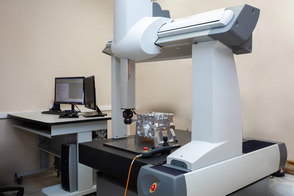
2. The Metrology Lab and Thermal Stabilization Protocols
Precision measurements are highly sensitive to thermal fluctuations. Aluminum has a high linear coefficient of thermal expansion (23 × 10-6 m/m°C). If a part is aggressively milled on a hot machine bed, it can easily reach a temperature of 45°C. If a machinist immediately measures the part with standard calipers on the shop floor, the metal will be thermally expanded. Once that part is loaded into a shipping crate and cools back down to a standard room temperature of 20°C, it will physically contract, shrinking out of specification.
Machined Hot (45°C):                     Cooled to Lab Standard (20°C):
     |<------- 100.05 mm ------->|            |<------- 100.00 mm ------->|
     +---------------------------+            +---------------------------+
     |     Expanded Aluminum     |            |    Stabilized Material    |
     +---------------------------+            +---------------------------+
A top-tier manufacturing partner addresses this by isolating their inspection process within a dedicated metrology laboratory held at a strict, continuous international standard of 20°C and under 50% relative humidity. Before critical tolerances are verified on a Coordinate Measuring Machine (CMM), the components must undergo a soak-out period, sitting inside the climate-controlled lab for at least 4 hours to eliminate internal thermal stresses and align with the CMM’s calibration coordinates. If a supplier lacks a climate-controlled inspection environment, they cannot claim to deliver reliable tolerances below ±0.01 mm.
3. Traceability, Materials Certification, and OQC Packages
The final stage of an elite quality loop is data validation. A reputable shop delivers more than just a box of finished metal; they provide a comprehensive documentation trail that protects your firm from liability.
[Raw Material Heat Lot] ---> [Material Test Report (MTR)] ---> [Milled Part Batch] ---> [Outbound Quality CMM Report]
Every delivery package should feature an explicit Outbound Quality Control (OQC) Report summarizing actual CMM measurement readouts against your target drawing specs. Furthermore, demand a Material Test Report (MTR) linked directly back to the original foundry heat lot of the raw metal block. This chemical analysis verification guarantees that the stock used to mill your parts is genuine, certified material rather than unrefined, low-cost scrap metal. Sourcing from a transparent partner ensures your procurement remains anchored in traceable quality data.
6. Conclusion: Balancing Design Theory with Machine Shop Floor Reality
Subtractive manufacturing is defined by strict physical boundaries. Every additional decimal place added to a tolerance block, every deep vertical cavity left un-optimized, and every poor choice of an overly stubborn alloy directly dictates machine cycle times, tool wear rates, and human labor costs.
True procurement efficiency is achieved by identifying the optimal balance between functional component performance and the physical realities of toolpaths and chip evacuation. By adjusting your engineering drawings to account for workholding setups, chip extraction vectors, and thermal expansion properties, your team can actively eliminate non-value-added premiums before a single tool touches material.
7. Frequently Asked Questions (FAQ)
Q1: When mapping out a new component project, how should I decide between general CNC machining and dedicated milling (cnc machining vs milling)?
A: “CNC machining” is a broad umbrella term encompassing all computerized, automated machine equipment controlled by digital code, including CNC laser cutters, plasma torches, Swiss-style lathes, and grinding systems. CNC milling is a specific subset within this family where the raw material block remains rigidly fixed to a stationary worktable while a high-speed cutting tool rotates to remove material. If your part is cylindrical, symmetrical, and requires high-speed external spinning, it belongs on a CNC Lathe (Turning). If your component features complex, non-symmetrical block geometries, deep pockets, flat mounting surfaces, or intricate multi-angled cutouts, it requires a dedicated milling machine.
 CNC Machining (Broad Umbrella)
  ├── CNC Turning (Rotational workpiece, fixed tool)
  └── CNC Milling (Stationary workpiece, rotating tool)
Q2: Why is Aluminum 6061-T6 consistently preferred for structural enclosures over lower-cost cast aluminum options?
A: Cast aluminum is produced by pouring molten metal into a mold, a process that frequently leaves microscopic air pockets (porosity), sand occlusions, and irregular internal crystalline grain structures within the core of the metal. If you attempt to mill high-precision, thin-walled cavities or deep threaded mounting holes into a cast component, the toolpath will unexpectedly strike these internal structural voids. This causes the cutting edge to catch, creating severe vibration, marring the internal surface finish, and frequently causing tool breakage. Aluminum 6061-T6 is a wrought, extruded billet alloy that has undergone intense mechanical rolling and thermal tempering. Its structure is dense, perfectly uniform, and free of internal voids, allowing cutting tools to maintain clean, predictable engagement with the material.
Q3: Why do suppliers apply high cost premiums when machining Stainless Steel 316 compared to standard carbon steels?
A: The premium is driven entirely by the material’s structural tenacity and its high rate of work-hardening. Stainless steel 316 contains significant levels of chromium, nickel, and molybdenum. These elements provide exceptional corrosion resistance but also make the metal incredibly gummy and tough to shear. As a tool moves through 316, the metal deforms elastically before shearing, generating extreme friction and concentrated heat that transfers directly back into the tool edge. To prevent the tool tip from melting or work-hardening the base metal into an un-machinable crust, the machine must run at lower cutting speeds and execute heavy, deliberate feeds. This extends total part run times significantly, driving up the machine-hour cost on the production floor.
Q4: If a design features multiple angled holes across four faces, how can I determine whether to seek a 3-axis VMC supplier or a 5-axis CNC machining partner?
A: The decision is driven by a trade-off between volume and required precision. To machine those multi-faced holes on a 3-axis VMC, a technician must physically stop the machine after completing the first face, manually unclamp the component, rotate it manually to align with a custom angled angle-plate fixture, re-locate the coordinate zero-point, and restart the cycle. This process must be repeated for every single face. If you are only producing two prototype units, the manual setup labor on a 3-axis VMC is often more economical than paying an engineer to program a full 5-axis simultaneous toolpath. However, if you are scaling up production or require strict positional alignment between those multi-faced holes, a 5-axis CNC machining approach is essential. The multi-axis machine eliminates manual relocation errors, completing all faces in a single continuous setup, ensuring absolute geometric accuracy across the lot.
Navigating the complexities of axis limits, material tolerances, and design constraints requires deep technical alignment between your engineering team and your production house. If you are preparing a complex new assembly, optimizing a legacy product line for volume production, or seeking an expert team to evaluate your technical drawings, reach out to our engineering group. We provide high-depth, data-driven DFM analysis and precision cnc machining milling services designed to bring your structural concepts to physical reality at an optimized production cost.


