
Oil and gas equipment does not give a machined part much room for error. A component may need to contain pressure, maintain a seal, guide another component, control fluid flow, or keep two mating parts aligned while exposed to corrosion, heat, vibration, or repeated loading.
That is why CNC machining for the oil and gas industry is not simply a matter of cutting a part to a drawing. The manufacturing route has to reflect what the part is required to do.
A bore, thread, sealing face, hole pattern, or shaft diameter may look like just another dimension on a drawing. In service, however, each can have a very different function. Understanding that difference is where precision machining becomes useful.
Why Oil and Gas Parts Require a Different Approach to CNC Machining
The working environment is one obvious difference. Oil and gas equipment can encounter pressure, temperature changes, corrosive fluids, abrasive particles, and, in some applications, sour-service conditions. Current industry machining guides commonly emphasize material selection, dimensional control, sealing surfaces, and documentation because these requirements are closely connected to component performance.
But the environment alone does not determine how a part should be machined.
The more useful question is:
What does the component have to do in that environment?
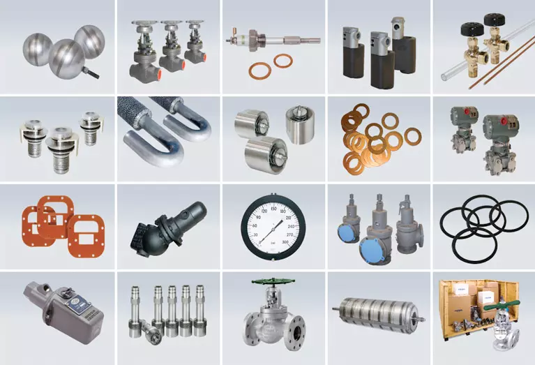
A valve component may need to control flow and maintain a sealing interface. A shaft may need to rotate while maintaining concentricity with a mating bore. A manifold may need several intersecting passages to connect correctly. A flange may depend on its face, bolt-hole pattern, and bore remaining in the correct relationship.
These functions create different manufacturing priorities.
For that reason, an oilfield machining job should not be approached by simply applying the tightest possible tolerance to every dimension. The functional features should determine where tighter control, better surface finish, and more detailed inspection are justified.
How Part Function Shapes Machining Requirements
A useful way to look at an oil and gas component is to separate its dimensions into three groups:
What locates the part? What allows it to function? What allows it to connect or seal?
A mounting face may establish a datum. A bore may locate a shaft. A thread may connect another component. A sealing face may control leakage. A cross-hole may provide a fluid path.
Those features do not necessarily require the same machining strategy.
For instance, tightening a non-functional external dimension may add machining time without improving the part’s performance. In contrast, a small error in a bore diameter, hole position, or mating surface can affect assembly or operation.
This is why functional tolerancing matters more than simply making every dimension as small as possible.
The same principle applies to surface finish. A surface that never contacts another component does not automatically need the same finish as a sealing or sliding surface.
This approach also helps control manufacturing cost. Precision is valuable where it protects function; unnecessary precision can simply increase inspection and machining time.
Where Precision Matters Most in Critical Features
Precision CNC machining becomes particularly important where several features have to work together.
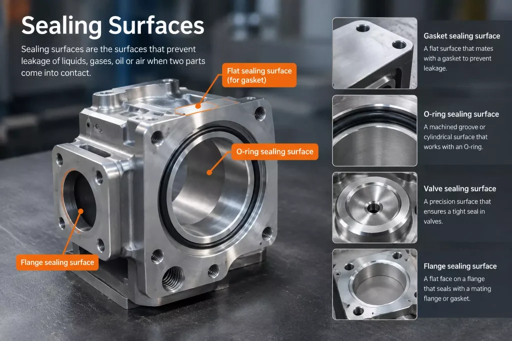
Sealing surfaces
A sealing face is not just a flat surface. Its dimensional size, flatness, surface condition, and relationship with the mating component can all matter.
The required surface finish also depends on the type of sealing system. There is no single Ra value that is appropriate for every seal, gasket, or metal-to-metal interface. Current industry guidance similarly emphasizes that tolerance and surface requirements should be tied to the actual function rather than applied uniformly.
Bores and mating diameters
A bore may locate a shaft, guide a moving component, contain a bearing, or control clearance.
That means diameter alone may not tell the whole story. Depending on the application, concentricity, cylindricity, straightness, or the relationship between the bore and another datum can become important.
Threads
A thread is another feature where “close enough” is not a useful manufacturing standard.
Thread form, pitch diameter, major/minor dimensions, and the relationship between the thread and the component’s other features all affect assembly.
Hole patterns
On a flange or mounting component, the individual hole diameters may be relatively straightforward to machine. The more important issue can be their location relative to the datum or central bore.
A hole can be correctly sized and still create an assembly problem if its position is wrong.
This is why the most important CNC machining dimensions are often relationships between features, rather than isolated numbers.
Matching the Machining Process to Part Geometry
The geometry of the part should influence the machining route.
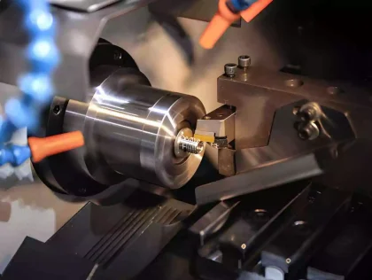
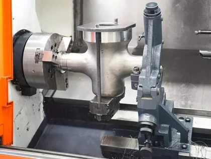
CNC turning is naturally suited to rotational features such as shafts, sleeves, bores, steps, and diameters. CNC milling becomes more useful when a component contains pockets, slots, ports, mounting faces, or non-rotational geometry.
More complicated components may combine both.
A part that contains a turned outer diameter, internal bore, side slot, and cross-hole may require several machining operations. Where appropriate, a turn-mill or carefully planned multi-operation process can reduce unnecessary handling.
Five-axis machining can become useful when several faces or angled surfaces need to be accessed without repeatedly repositioning the component. The benefit is not simply that a machine has “five axes.” The real question is whether the geometry and feature relationships justify that capability.
A practical manufacturing review therefore starts with:
geometry → tool access → setup → machining operation → inspection
That sequence is more useful than choosing a machine based only on the overall appearance of the component.
How Material Choice Changes the Machining Process
Material selection in oil and gas applications is normally driven by service requirements such as corrosion resistance, strength, temperature, pressure, and fluid exposure. Commonly discussed materials include stainless steels, duplex stainless steels, nickel alloys, alloy steels, and titanium alloys.
But the material does not stop influencing the job once the purchasing decision is made.
It changes how the material needs to be machined.
Nickel-based alloys such as Inconel can introduce high cutting temperatures, work hardening, and accelerated tool wear. Duplex stainless steels combine corrosion resistance with relatively high strength, which can make machining more demanding than a conventional stainless grade.
17-4 PH stainless steel also behaves differently depending on its material condition and heat-treatment state.
For the machinist, this means that material selection can affect:
- cutting conditions
- tool selection
- chip control
- heat management
- tool life
- cycle time
- dimensional stability
This is an important distinction between selecting a material for service and successfully machining that material into a stable finished component.
The Hidden Machining Challenges in Complex Parts
Some oilfield parts are difficult to manufacture for reasons that are not obvious from the outside.
Deep bores
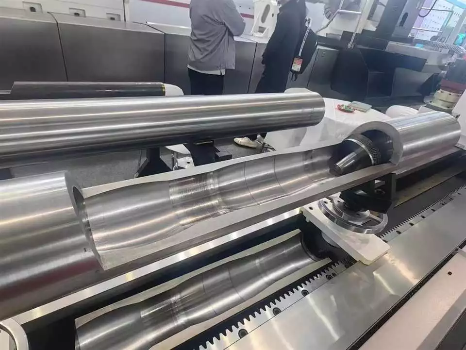
A deep bore introduces tool overhang, deflection, chip evacuation, and access considerations. The deeper the feature becomes relative to the tool diameter, the more important the machining strategy becomes.
The challenge is not simply making a hole deeper.
It is maintaining the required geometry at the bottom of that hole while removing material efficiently.
Intersecting passages
Manifolds and fluid-control components can contain multiple intersecting passages.
Machining the individual holes may be straightforward. The difficult part is maintaining their locations and dealing with the intersection where drilling, boring, deburring, and cleaning requirements meet.
Thin walls
Thin sections can move under cutting forces or lose dimensional stability during machining.
In those cases, the workholding strategy becomes part of the manufacturing problem. Removing too much material too quickly can change the shape of the remaining section.
Long shafts
Long slender components introduce deflection and runout concerns. Supporting the workpiece and controlling the relationship between multiple diameters can become more important than simply reaching the target diameter.
Difficult alloys
Hard-to-machine materials add another layer of difficulty because cutting heat, work hardening, and tool wear can affect both productivity and dimensional consistency.
These are the kinds of issues that often determine whether a part is straightforward or time-consuming to machine.
Machined Parts Used Across Oil and Gas Operations
CNC machining is used for a broad range of components across drilling, production, fluid handling, processing, and related equipment. Common examples include valve components, manifolds, flanges, fittings, shafts, sleeves, housings, pump components, and downhole components.
The more useful way to classify these parts, however, is by what they need to accomplish.
Flow-control components may require accurately machined ports, bores, seats, and sealing features.
Manifolds can combine multiple ports and intersecting passages, making hole location and internal access important.
Flanges and adapters depend on the relationship between faces, bores, bolt-hole patterns, and threads.
Shafts and sleeves rely more heavily on diameter, concentricity, runout, surface finish, and mating conditions.
Housings and downhole components can introduce deep internal features, difficult materials, complex geometries, or restricted tool access.
This is why “oil & gas machining components” should not be treated as one uniform category. The machining priorities change with the function of the part.
Why a Simple Part Can Still Take More Time to Machine
Visual complexity is not a reliable way to estimate machining cost.
A relatively simple-looking component can require more machining time than a visibly complicated part if it combines a difficult material, deep internal features, tight functional tolerances, multiple setups, special surface requirements, and detailed inspection.
Quantity also changes the calculation.
A low-volume component may require substantial setup and programming time that cannot be spread across hundreds of parts. A repeat order can become more efficient once the process, tooling, fixtures, and inspection approach have already been established.
This is one reason an RFQ should be evaluated from the manufacturing process rather than from the external shape alone.
A useful cost question is not:
“How complicated does this part look?”
It is:
“How many manufacturing steps are required to produce and verify the features that matter?”
Making the First Part Accurate Is Only the Beginning
Producing one accurate component is different from producing the same component repeatedly.
On repeat orders, tool wear, setup consistency, material variation, inspection methods, and process stability all begin to matter.
The first part establishes whether the process can achieve the required dimensions. Subsequent parts test whether the process can continue to achieve them.
That distinction becomes important when a component moves from prototype or replacement production into recurring orders.
A stable process should make it possible to reproduce the critical features without treating every new batch as if it were a completely new job.
For oilfield machining, this repeatability can matter just as much as the nominal tolerance on the first component.
What a Drawing May Leave Open Before Machining Begins
A drawing can define the geometry of a part without answering every manufacturing question.
Before machining begins, several details may need to be clear:
- material grade and condition
- critical dimensional tolerances
- datum references
- thread requirements
- sealing surfaces
- surface finish
- heat treatment
- coating or finishing
- inspection requirements
- quantity
- documentation requirements
This becomes especially important when a drawing contains a mixture of general tolerances and a small number of critical callouts.
The machining team needs to understand which features control the function of the component and which dimensions are secondary.
A good manufacturing review is therefore more than checking whether a CAD model can be loaded into CAM software. It is about identifying the features most likely to affect machining, inspection, assembly, and final use before material is cut.
Inspecting the Features That Matter
Inspection should follow the function of the part.
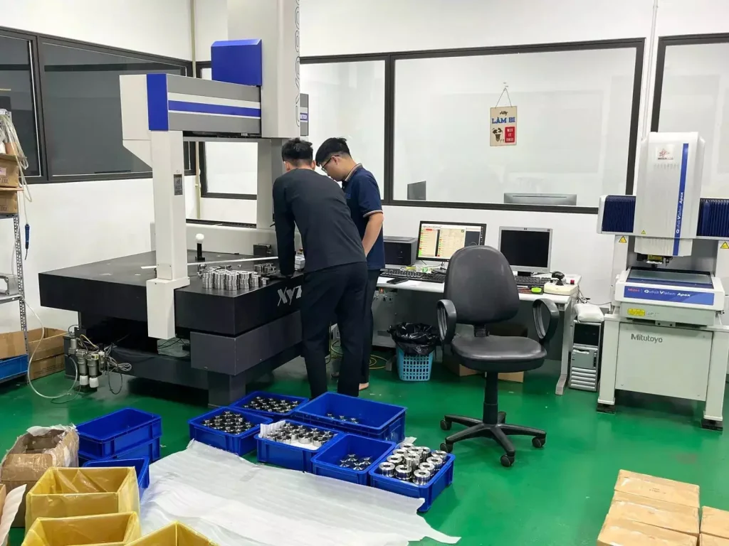
A CMM is particularly useful when the relationship between several features matters—for example, the position of a hole pattern relative to a datum or the relationship between a bore and a mounting face.
A height gauge can be useful for datum-related heights, steps, and dimensional relationships.
Thread gauges can verify whether a specified thread meets the applicable acceptance requirement.
Surface-finish measurement becomes relevant when a particular surface has a defined functional requirement.
The point is not to inspect everything in exactly the same way.
It is to identify the characteristics that matter and use an inspection method capable of verifying them.
For applicable features, CNC machining capability can reach ±0.01 mm, with surface finishes down to Ra 0.8 μm where specified by the drawing and process requirements. These figures should be understood as applicable machining capabilities, not as a blanket tolerance or surface-finish guarantee for every feature.
When the Original Part Exists but the Drawing Does Not
Replacement machining presents a different problem from producing a new component from a complete drawing.
Sometimes the physical part is available while the original drawing, CAD model, or manufacturing data is incomplete.
In that situation, the job starts with understanding the existing component.
Critical dimensions, interfaces, bores, threads, mounting features, and other functional characteristics need to be identified before a new manufacturing model is created.
The general process can be:
existing part → dimensional measurement → CAD reconstruction → manufacturing planning → CNC machining → inspection
This is where reverse engineering can become useful for oilfield replacement parts.
The objective is not to copy every visible dimension blindly. It is to determine which features control fit and function, reconstruct the part accordingly, and then manufacture the replacement with measurable acceptance criteria.
For equipment where the original component is no longer readily available, this approach can be more practical than starting from a missing drawing and guessing the original design intent.
What Determines Cost and Lead Time?
Several factors can affect the price and delivery time of an oil and gas CNC machining project.
Material affects both raw material cost and machining behavior.
Tolerance affects process control and inspection.
Geometry determines tool access, setups, and machining time.
Deep holes and internal features can require slower or more controlled operations.
Surface finish may require additional passes or secondary processing.
Quantity determines how setup and programming costs are distributed.
Inspection and documentation add work when a project requires detailed dimensional reports or material records.
This is why two parts with similar dimensions can receive very different quotations.
A practical RFQ should provide the available drawing or 3D model, material, quantity, critical tolerances, surface requirements, secondary processes, inspection requirements, and delivery expectations.
The clearer those requirements are, the less uncertainty there is between quoting and production.
CNC Machining Capabilities for Oil and Gas Applications
Oil and gas machining requires more than a machine capable of removing material. The process needs to connect the drawing, part function, machining method, and inspection requirements.
At MS Machining, available CNC machining services include milling, turning, and 5-axis machining for applicable geometries. Parts can be supplied from customer-provided STEP, STP, IGES, X_T, DWG, or PDF data.
For applicable features, machining capability can reach ±0.01 mm, with surface finishes down to Ra 0.8 μm where specified. Inspection resources include CMM, height gauge, and thread gauge.
For a new component, the process can start from a drawing or 3D model. For a replacement component with incomplete documentation, reverse engineering can be considered to reconstruct the manufacturing information before machining.
The goal is straightforward: understand what the part has to do, identify the features that control that function, choose a practical machining route, and verify the dimensions that matter.
For an oil and gas CNC machining project, send the available drawing, 3D model, material, quantity, and critical requirements for quotation.

Frequently Asked Questions
1. What Types of Oil and Gas Parts Can Be CNC Machined?
CNC machining can be used for a wide range of custom parts, including valve components, manifolds, flanges, shafts, sleeves, housings, fittings, and other precision-machined components. The suitable machining process depends on the part geometry, material, critical features, and production requirements.
2. What Materials Are Suitable for Oil and Gas Machining?
Common material choices include stainless steels, alloy steels, duplex and super duplex stainless steels, nickel-based alloys, and titanium. Material selection depends on the operating environment, required strength, corrosion resistance, temperature, and pressure. The material grade and heat-treatment condition can also affect tool selection and machining parameters.
3. What CNC Machining Tolerances Can Be Achieved for Oil and Gas Parts?
For applicable features, machining capability can reach ±0.01 mm. The achievable tolerance depends on the part geometry, material, feature size, machining process, and drawing requirements. A ±0.01 mm capability should not be interpreted as a blanket tolerance for every dimension.
4. How Are Critical Features on CNC Machined Parts Inspected?
Inspection methods are selected according to the feature being checked. CMM inspection can verify dimensional and positional relationships, while height gauges can be used for datum-related dimensions and steps. Thread gauges can check specified threads, and surface-finish measurement can be used where a defined surface roughness is required.
5. Can Replacement Oilfield Parts Be Made Without the Original Drawing?
Yes, provided there is enough dimensional information to reconstruct the part. An existing component can be measured and used to rebuild the geometry, followed by CNC machining and inspection. This approach is useful when replacement parts are needed but the original drawing or CAD model is unavailable.
6. What Information Is Needed for an Oil and Gas CNC Machining Quote?
A drawing or 3D CAD model, material specification, quantity, critical tolerances, surface-finish requirements, and any secondary processing or inspection requirements provide the main information needed for quotation. If the part is a replacement component without drawings, measurements, photos, or an existing physical sample can help define the m