
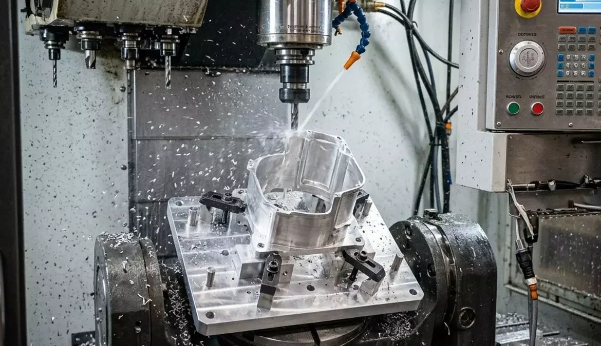
A thin-wall housing does not become difficult simply because one wall is 1.2 mm thick. The real difficulty is how the part changes as material is removed.
A housing can begin as a rigid aluminum billet and finish as a structure with walls only slightly over 1 mm thick. During that transition, the stiffness of the workpiece changes continuously. A floor that was stable during roughing can become flexible after the surrounding pocket is opened. A bearing bore can lose support as material is removed around it. A sealing surface can develop chatter even though the programmed dimensions are correct.
For a precision housing, these effects are connected.
This is why we do not evaluate a thin-wall part from its minimum wall thickness alone. We look at the drawing and 3D model together, trace the critical dimensions back to their datums, and determine how the workpiece is likely to behave at each stage of machining.
The following is a representative example of the type of aluminum housing that requires this approach. The dimensions are provided to illustrate the machining considerations involved and do not represent a customer-specific drawing.
A Representative Thin-Wall Aerospace Housing
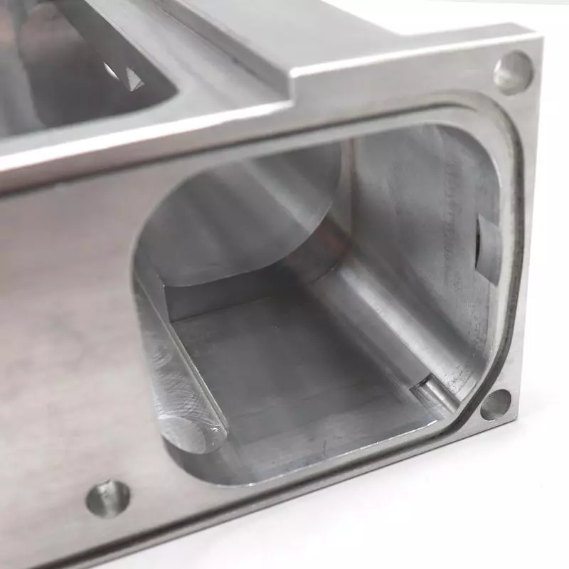
Consider a 7075-T6 aluminum housing approximately 180 × 120 × 45 mm.
The overall geometry is typical of a precision structural housing: internal pockets, mounting features, a bearing bore, a register and a sealing surface.
The difficulty comes from the way these features are arranged.
The main floor is approximately 1.2 mm thick and serves as the primary reference surface. One internal wall is also approximately 1.2 mm thick, but extends about 28 mm from its supporting structure. A Ø32 mm bearing bore is located near a thin register, creating a tightly controlled relationship between features supported by a relatively flexible section of the housing.
The sealing surface requires Ra 0.8 μm.
None of these requirements is unusual by itself.
The problem is their interaction.
The 1.2 mm floor is not simply a thin section. It is a datum. The Ø32 bore is not simply a hole. Its location depends on the stability of the surrounding structure. The 1.2 × 28 mm wall is not simply a thin wall. Its stiffness changes as the adjacent pocket is machined.
That is what makes this a process-planning problem rather than a simple milling job.
Reading the Part Before Programming It
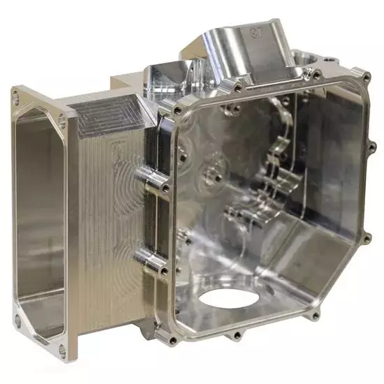
When a thin-wall part comes in, we do not start by asking how thin the minimum wall is. We first trace the important dimensions back to their reference surfaces.
In this housing, the primary reference is the large floor at the bottom of the main pocket. At the beginning of machining, that area is supported by a substantial amount of aluminum. Later in the process, most of that material will be removed, leaving only the final thin floor.
This creates two very different machining conditions.
Early in the job, the floor is relatively rigid. Later, it is a flexible section of aluminum.
That difference matters because the same fixture force can have very different effects at those two stages. A clamping force that is insignificant against the original billet can become enough to distort a 1.2 mm floor once the surrounding material has been removed.
For this reason, we do not assume that a surface is stable simply because it can be probed as flat while clamped.
The question is what happens when the support is removed.
That distinction becomes especially important when the drawing specifies a flatness or positional requirement from that surface. If the customer needs the housing to meet the requirement in its free state, the machining process has to be designed around the free-state geometry rather than the geometry created by the fixture.
This is one of the first things we look for when reviewing a drawing. A tight tolerance on a flexible surface is not automatically difficult. A tight tolerance on a flexible surface that also controls several other features is where the process becomes sensitive.
1. Start With the Datum, Not the Thinnest Wall
The first feature we examine is the main floor.
At the beginning of machining, this area is supported by a large volume of aluminum. The billet behaves relatively rigidly, and the fixture can establish a stable reference without significantly affecting the geometry.
After the internal pocket is opened, the situation changes.
The final floor is only about 1.2 mm thick. The same clamping force that had little influence on the original billet can now deflect the remaining floor.
This creates an important distinction between machined geometry while restrained and geometry after the part is released.
If the fixture forces the floor flat, the machine can finish the surface and the probe can report an acceptable result while the part is still clamped. Once the clamps are released, the floor can recover toward a different shape.
That movement matters because Datum A is not isolated.
If the bearing bore, mounting holes, register or sealing features are dimensioned from that datum, movement of the floor can change the relationship of those features to the rest of the component.
The important question is therefore not:
Can the machine produce a flat 1.2 mm surface?
It is:
Can the process produce that surface in the condition in which the drawing requires it to function and be inspected?
If the requirement applies to the free-state part, the process must account for free-state geometry rather than relying on the fixture to create the required condition.
2. The 1.2 × 28 mm Wall Is a Structural Problem
The tall internal wall is more visually obvious as a thin-wall feature.
At approximately 1.2 mm thick and 28 mm high, its height-to-thickness ratio is roughly 23:1.
But the ratio alone does not determine whether the wall will machine successfully.
We also need to consider:
- unsupported wall length
- pocket depth
- remaining stock
- cutter diameter
- tool extension
- cutting engagement
- wall support
- the condition of the opposite side of the pocket
A 1.2 mm wall surrounded by substantial material is very different from a 1.2 mm wall standing beside a large open pocket.
During roughing, the future wall is still connected to surrounding stock. That stock provides stiffness and helps absorb cutting forces.
As the pocket becomes deeper and wider, that support disappears.
The wall is therefore not the same mechanical structure at the beginning and end of the operation.
This is why taking the wall directly to its final thickness during early roughing can create problems. The part becomes flexible before the rest of the geometry is ready for finishing.
Instead, the thin section is normally kept thicker during the earlier stages. The surrounding material is removed while the housing still retains sufficient stiffness, and the final wall thickness is established later.
The exact remaining stock cannot be reduced to a universal rule such as “leave 0.5 mm.” It depends on the geometry and machining conditions.
The principle is more important than the number:
Do not create the most flexible version of the workpiece before the process is ready to control it.
3. The Bearing Bore and Register Must Be Treated as One Feature System
The Ø32 mm bearing bore is where the drawing becomes more demanding.
The bore itself is not particularly difficult because it is 32 mm in diameter. A CNC machine can produce a controlled bore size.
The more important question is what supports the bore.
The bore is located near a thin register and a relatively thin section of the housing. If material is removed from this area, the local stiffness changes.
This means the bore and register cannot always be treated as two independent machining operations.
Imagine the following sequence:
- Rough the surrounding pocket.
- Finish the Ø32 bore.
- Release the part.
- Machine the register in another setup.
Each individual operation may produce an acceptable measurement.
The problem is that the relationship between the two features can change when the workpiece is repositioned or released.
A bore can therefore be within its dimensional tolerance while the relationship between the bore, register and primary datum is outside the drawing requirement.
This is a common distinction between size control and geometric control.
For a thin-wall housing, controlling the diameter is only part of the job. The supporting structure and the relationship between functional features have to remain stable as well.
Where geometry and tool access allow, we prefer to keep closely related features within the same controlled machining sequence rather than creating unnecessary setup changes.
The reason is not simply to reduce the number of setups.
It is to reduce opportunities for the workpiece to change between the operations that establish the functional relationship.
4. Roughing Should Preserve the Structure of the Part
Roughing removes the largest volume of material, so it has the greatest influence on the final stiffness of the housing.
The objective is not to make the part look as close as possible to the final CAD model as quickly as possible.
The objective is to remove material while maintaining a predictable workpiece condition.
For this housing, the internal pockets are therefore treated as structural changes rather than simply empty volumes.
Opening one pocket completely can turn a previously rigid section into a flexible wall. Removing a large amount of material from one side can also change the balance of residual stress in the remaining material.
The exact roughing sequence depends on the geometry, but the principle is consistent:
The part should lose stiffness in a controlled way.
Large cutters can remove material efficiently during roughing, but they do not need to establish the final thin-wall geometry at this stage.
Leaving controlled stock around the critical walls provides temporary support and allows high-material-removal operations to take place while the workpiece is still relatively rigid.
Semi-finishing then reduces the remaining stock and brings the geometry closer to its final condition.
This is more predictable than creating a fully flexible wall early in the process and then expecting the finishing operation to compensate for the resulting movement.
5. The Starting Blank Affects the Final Part
Thin-wall machining starts before the first toolpath.
The starting billet needs to provide enough material for the finished geometry while allowing the machining sequence to remain balanced.
An excessively large blank increases material removal and cutting time. A blank that is too close to the final profile can limit workholding options and reduce the amount of material available to support thin sections during later operations.
Material condition also matters.
7075-T6 is widely used for structural aluminum components because of its high strength-to-weight ratio. However, machining away a substantial portion of a billet changes the stress balance within the remaining component.
This does not mean every 7075-T6 billet will move by a predictable amount.
It means the process should not assume that the final geometry will remain unchanged simply because the CNC machine has followed the programmed coordinates accurately.
For a housing with large pockets and thin remaining sections, the following factors are connected:
starting blank → material removal → residual stress → stiffness → clamping response → final geometry
That is why the blank selection, CAM strategy and workholding strategy should be considered together.
6. The First Setup Should Establish Stability
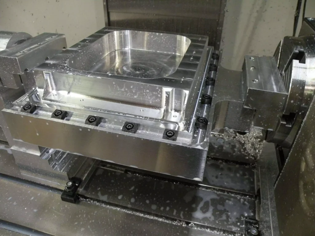
The first setup is not about removing as much material as possible.
It is about creating a reliable reference while keeping the workpiece sufficiently supported.
The fixture should primarily engage stronger sections of the billet. Where the geometry permits, larger contact areas or soft jaws can distribute the holding force rather than concentrating it against future thin sections.
Additional support can also be considered beneath areas that will eventually become thin.
The important point is that the fixture should hold the part without unnecessarily changing the geometry that the process is supposed to produce.
If a 1.2 mm floor has to be physically forced into a flat condition by the fixture, the process is already controlling the wrong geometry.
The first setup is therefore used to establish reference surfaces and remove bulk material while the housing still has substantial structural support.
Those initial references do not necessarily represent the final functional surfaces.
They provide the controlled starting point for the subsequent operations.
7. Semi-Finishing Is Where the Workpiece Condition Becomes Critical
After roughing, the housing has lost a significant amount of material and therefore a significant amount of stiffness.
This is where semi-finishing becomes important.
The purpose of semi-finishing is not simply to remove another layer of stock.
It is to bring the remaining material under control before the final functional surfaces are established.
For this housing, that can mean:
- bringing the pocket floors closer to final depth
- reducing wall stock evenly
- preparing the area around the bearing bore
- controlling the remaining material around the register
- maintaining enough support for the final thin-wall operations
At this stage, an intermediate inspection can be valuable.
The purpose is not only to determine whether the part passes.
It is to determine whether the workpiece is behaving as expected.
If the main floor moves significantly after release, that information is more useful before the final bore and sealing surfaces are finished than after the entire component has been completed.
Thin-wall machining is therefore not always a simple sequence of:
rough → finish → inspect
A more controlled process can be:
rough → release/check → semi-finish → verify workpiece condition → finish critical features → final inspection
The exact sequence depends on the drawing and geometry, but the principle is to identify deformation before it becomes embedded in the final features.
8. Releasing the Fixture Can Change the Geometry
This is one of the defining characteristics of thin-wall machining.
Consider the 1.2 mm floor.
While clamped, the fixture provides support. The surface can appear flat and stable during machining.
Once the fixture is released, the elastic deformation caused by clamping disappears.
The measured geometry can therefore change even though no cutting operation has taken place.
This is not necessarily a machine accuracy problem.
Changing the CNC coordinate system does not automatically solve a deformation problem.
The process needs to distinguish between:
- cutting error
- tool deflection
- fixture-induced deformation
- residual-stress movement
- free-state recovery
This distinction also affects inspection.
If the drawing requires a free-state condition, the component cannot simply be forced into position during measurement and treated as representative of the finished part.
If a restrained inspection condition is required, the restraint needs to be defined and reproduced consistently.
For flexible components, inspection condition is part of the manufacturing requirement, not merely a measurement detail.
9. Finish the Bore When the Supporting Structure Is Ready
The bearing bore should be finished after the surrounding structure has reached an appropriate level of stability.
The reason is straightforward.
A precision bore is controlled not only by its diameter but also by its relationship to the datum structure and adjacent functional features.
If the surrounding wall moves after the bore has been finished, the bore’s size may remain correct while its functional position changes.
This is especially important when the drawing contains a tight geometric relationship between the bore, register and datum.
The finishing operation therefore needs to be placed at a point in the process when:
- the major material has already been removed
- the supporting structure is close to its final geometry
- the remaining stock is controlled
- the fixture is not unnecessarily distorting the critical section
- the tool can access the feature with adequate rigidity
The objective is not simply to make a Ø32 mm hole.
It is to establish the bearing interface relative to the rest of the housing.
10. A Correct Bore Diameter Does Not Guarantee a Correct Part
This distinction is important when reviewing inspection results.
Suppose the drawing specifies a Ø32 mm bearing bore with an H7 fit.
The measured bore diameter is within the H7 range.
That confirms the bore size.
It does not automatically confirm:
- bore location
- bore orientation
- bore-to-datum relationship
- bore-to-register relationship
- overall functional alignment
A thin-wall housing can therefore produce an inspection report where the bore diameter is correct but the part still fails a geometric requirement.
This is why adjusting the bore size alone may not solve the problem.
If the supporting structure has moved, the process needs to address the source of that movement.
For this type of component, the inspection strategy should follow the functional structure of the drawing rather than treating every dimension as an independent number.
11. Tool Extension Can Become a Limiting Factor
The 28 mm tall internal wall also affects tool selection.
The first question is not simply whether the cutter can physically reach the bottom of the feature.
The question is whether it can reach the feature with sufficient rigidity.
A long tool extension increases deflection. When the tool is flexible and the workpiece is also flexible, the two systems can interact.
This can produce:
- dimensional variation
- wall deflection
- poor surface finish
- vibration
- inconsistent results between parts
A shorter, more rigid tool is generally preferable when the geometry allows it.
This is one area where five-axis machining can sometimes provide a practical advantage.
The benefit is not simply having two additional rotary axes. A different tool orientation may provide better access to the surface and reduce the required tool extension.
That can improve rigidity and reduce the amount of unsupported cutting length.
Five-axis machining is therefore useful when the geometry benefits from improved tool orientation, access or rigidity. It is not automatically the answer to every thin-wall problem.
12. Chatter Is Usually a System Problem
When chatter appears on a thin wall, the first reaction is often to change spindle speed or feed.
Those parameters matter, but they may not be the root cause.
If the wall was made too flexible during roughing, if the remaining stock is uneven, if the tool extension is excessive, or if the fixture does not adequately support the workpiece, the final finishing operation is starting from an unstable condition.
The cutter then becomes part of a mechanical system involving:
tool → holder → spindle → workpiece → fixture
If one part of that system is too flexible, changing RPM alone may only move the vibration to a different cutting condition.
For a sealing surface requiring Ra 0.8 μm, this becomes particularly important.
The finishing cutter cannot reliably produce a controlled surface if the wall underneath it is moving.
The response may involve:
- reducing tool extension
- improving wall support
- changing the remaining finishing stock
- modifying the preceding semi-finish operation
- changing cutting direction
- reducing radial engagement
- adjusting cutting parameters after mechanical stability has been established
The important distinction is:
Chatter control starts with stiffness and support. Cutting parameters come after that.
13. Finish the Sealing Surface After the Structure Is Stable
The Ra 0.8 μm sealing surface is another feature that should be considered in relation to the surrounding structure.
Surface finish is not independent of workpiece rigidity.
If the wall or surface underneath the cutter deflects, the finishing pass can leave a periodic surface pattern even when the programmed depth is correct.
The final operation therefore needs controlled remaining stock, appropriate tool extension and sufficient support behind the cutting area.
A finishing pass should remove a relatively small and predictable amount of material.
It should not be expected to correct a large amount of stock or compensate for movement created by earlier operations.
If vibration can be heard during the finish cut, the surface condition is already indicating that the process needs attention.
The goal is not to find a cutter that can overpower the flexible wall.
The goal is to make the wall stable enough that the finishing cutter does not have to fight it.
14. The Main Datum Should Be Finished at the Right Stage
The primary floor presents a sequencing problem.
If the 1.2 mm floor is finished too early, it becomes flexible while substantial machining remains to be completed.
If it is left completely unfinished until the end, the process may lack a sufficiently controlled reference for establishing the final functional features.
The solution is not a universal machining sequence.
The floor needs to move through controlled stages of roughing, semi-finishing and final finishing according to the surrounding geometry.
The key consideration is the amount of support available when each reference surface becomes functionally important.
This is why a generic instruction such as “finish the datum first” is not always sufficient for thin-wall components.
The datum itself may change stiffness during machining.
The correct sequence is determined by the relationship between the datum, surrounding material and critical features.
15. Drawing and 3D Model Need to Be Read Together
The drawing defines the engineering requirements.
The 3D model shows the physical structure that has to satisfy them.
For thin-wall machining, neither document tells the complete story by itself.
The drawing may identify the main floor as the primary datum and apply a tight geometric tolerance to the bearing bore.
The model may then reveal that the datum is only 1.2 mm thick and that the bore sits beside a deep pocket.
That combination changes the manufacturing strategy.
The same applies to tool access.
A drawing may specify an internal surface with a reasonable tolerance, while the model reveals that reaching it with a three-axis orientation requires excessive tool extension.
A different setup, tool orientation or five-axis approach may provide a more rigid solution.
This is why quoting a thin-wall housing from overall dimensions and material alone is risky.
The geometry determines the process.
16. Separate Functional Features From General Tolerances
A drawing may contain a general tolerance such as ±0.05 mm.
That does not mean every surface should receive the same machining strategy.
Consider two 1.2 mm walls.
The first is an external envelope wall with substantial support.
The second supports a bearing bore and connects to a sealing interface.
The nominal wall thickness may be identical.
The manufacturing risk is not.
The second wall directly influences functional geometry, so its stiffness, support and machining sequence deserve more attention.
This is why we separate the functional features from general dimensions during drawing review.
For this housing, the main areas of attention would include:
| Drawing feature | Manufacturing question |
|---|---|
| 1.2 mm Datum A floor | Will the surface remain stable after release? |
| 1.2 × 28 mm wall | How much support remains during final machining? |
| Ø32 H7 bore | Is the supporting structure stable when the bore is finished? |
| Thin register | Can its relationship to the bore be maintained? |
| Ra 0.8 μm seal face | Is the surface rigid enough for the final pass? |
| General ±0.05 mm dimensions | Are these functional or primarily envelope requirements? |
This is a more useful way to assess machining difficulty than simply counting how many dimensions are marked “tight.”
17. Inspection Should Follow the Function of the Housing
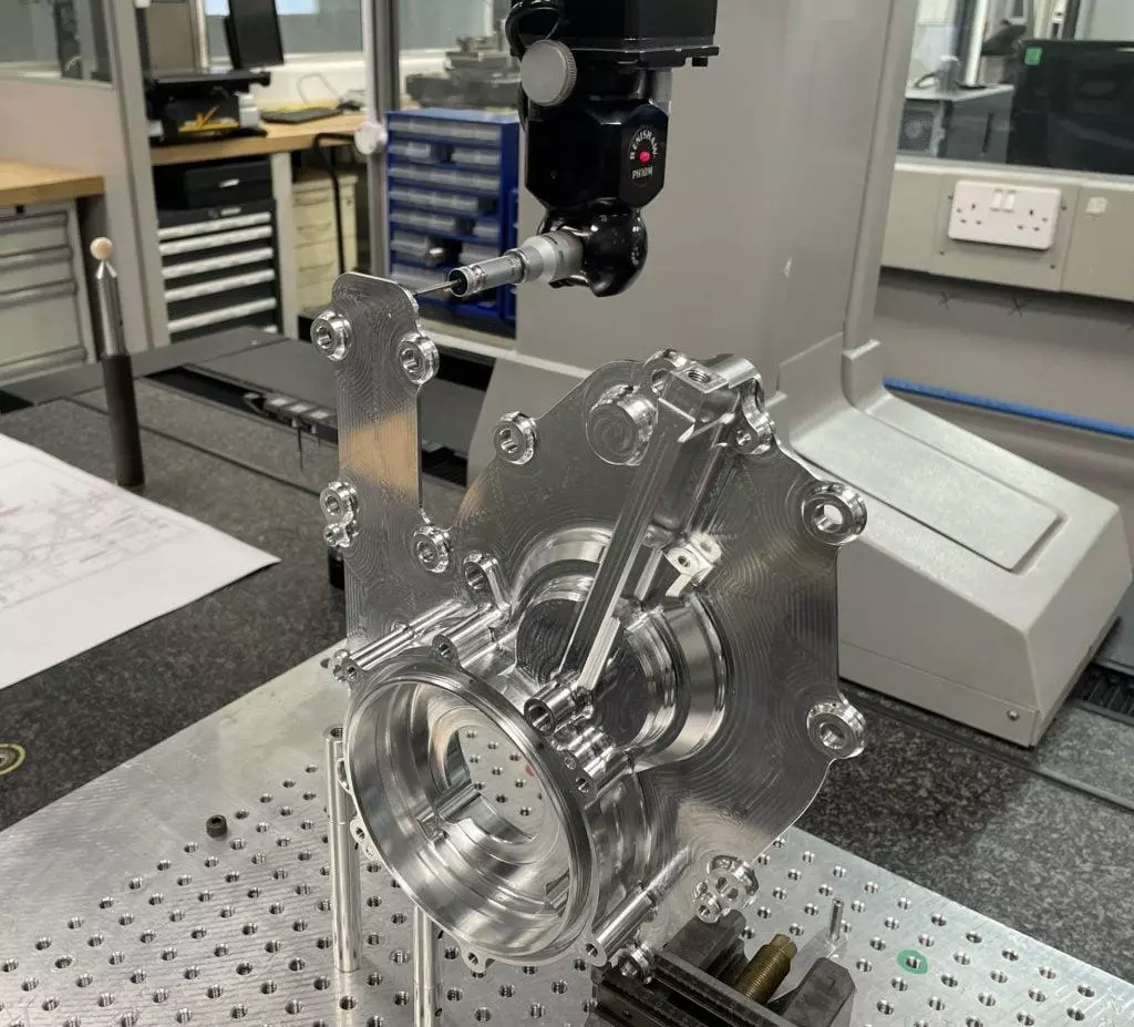
For a component with several geometric requirements, CMM inspection is useful because the critical requirements are not limited to simple size measurements.
The inspection program needs to establish the correct datum structure and evaluate the features according to the drawing.
But the CMM program cannot determine whether the part should be restrained during measurement.
That condition needs to come from the engineering requirement.
For example, if Datum A has a free-state flatness requirement, the part should not be forced flat during measurement.
If the customer specifies a restrained inspection condition, the fixture and restraint method need to be clearly defined.
This distinction becomes particularly important for thin floors.
A measurement can be highly repeatable and still fail to represent the physical condition of the component during assembly.
For first article inspection, the inspection condition should therefore be established before the final CMM program is released.
The objective is not simply to produce a report containing hundreds of measurements.
The report should describe the actual condition of the component relative to the drawing and its intended function.
18. First Article Inspection Is a Process Check, Not Just a Report
For a difficult housing, the first article provides information about the entire machining process.
The important questions are not limited to whether each individual dimension is inside its tolerance.
We want to understand whether the relationships between the features have remained stable.
For this housing, that includes:
- Does the main floor remain within its specified condition after release?
- Is the bearing bore correctly related to the primary datum?
- Does the register maintain its relationship with the bore?
- Does the 28 mm wall remain stable after the surrounding pocket is completed?
- Does the sealing surface achieve Ra 0.8 μm without chatter?
- Are the results repeatable without relying on excessive manual correction?
These questions are connected.
If the bore relationship changes after the housing is released, for example, the issue may not be the bore machining operation itself. The supporting structure may have changed.
This is why first article inspection should be used to validate the process, not merely to identify individual out-of-tolerance dimensions.
A process that produces one acceptable part through manual adjustment is not equivalent to a process that can repeatedly produce the same result across a production lot.
19. Why We Do Not Automatically Chase the Tightest Tolerance Everywhere
A drawing may contain a general tolerance such as ±0.05 mm across many dimensions.
That does not mean every wall should receive the same manufacturing strategy.
Some dimensions control the external envelope and have substantial structural support. Others control assembly relationships.
Those two groups should not automatically receive the same process.
The bearing bore, register, main datum and sealing surface deserve more attention because they directly affect function.
A non-functional pocket wall may have the same numerical general tolerance on the drawing but present a completely different machining risk.
This is why we separate the functional requirements from the general dimensions when reviewing the drawing.
It helps prevent two opposite mistakes.
The first is underestimating a critical feature because the nominal tolerance looks similar to other dimensions.
The second is spending unnecessary machining time treating every surface as if it were a bearing fit.
Good process planning is not simply about making everything as accurate as possible.
It is about putting the most control where the part actually needs it.
20. Where the Additional Machining Time Actually Goes
The extra time associated with thin-wall machining does not necessarily come from the final 1.2 mm wall cut.
It often comes from controlling the workpiece before that cut can be performed reliably.
Additional process time may be required for:
- workholding preparation
- controlled roughing
- semi-finishing
- intermediate inspection
- tool changes
- additional support
- controlled finishing stock
- critical feature machining
- final inspection
This is why two CNC suppliers can quote significantly different prices for the same aluminum housing.
One quote may primarily reflect machine time and material removal.
Another may include the process required to control workpiece deformation and verify the critical geometry.
For a component with tight geometric relationships, the relevant question is not simply:
How many hours is the machine running?
It is:
What manufacturing controls are included in those hours?
21. What We Review Before Quoting
For a conventional CNC component, a drawing and material specification may be sufficient for an initial estimate.
For a thin-wall housing, we prefer to review the 2D drawing and 3D model together.
The review focuses on:
- thin-wall regions
- datum structure
- critical GD&T
- bearing bores and registers
- sealing surfaces
- wall height and support
- material grade and temper
- tool access
- workholding options
- machining sequence
- inspection condition
- production quantity
We also want to distinguish functional features from general envelope dimensions.
A 1.2 mm wall that has no influence on assembly may require a different process from a 1.2 mm wall supporting a bearing interface.
If the inspection condition for a flexible feature is not defined, that should also be clarified before production.
It is better to resolve that question during drawing review than after a completed lot has already been inspected.
Thin-Wall Machining Is About Controlling the Workpiece
The CNC machine is only one part of the process.
Machine positioning accuracy matters, but the machine cannot prevent a flexible aluminum structure from moving when material is removed.
For a housing like the one described above, the manufacturing process has to control the workpiece from the starting billet through final inspection.
The starting blank needs to be appropriate for the amount and distribution of material removal.
The fixture needs to provide support without unnecessarily deforming thin sections.
Roughing needs to remove material while preserving enough stiffness for the later operations.
Semi-finishing needs to control the remaining stock and reveal how the workpiece is behaving.
The bearing bore and register need to be machined when their supporting structure is sufficiently stable.
Tool extension needs to be controlled rather than selected only according to reach.
Chatter needs to be treated as a mechanical stability problem rather than simply a spindle-speed problem.
And inspection needs to reproduce the condition defined by the drawing.
That is the difference between machining a thin wall and controlling a thin-wall component.
Frequently Asked Questions
What is thin-wall machining for aluminum housings?
Thin-wall machining refers to producing sections of a component where the remaining material is thin enough that cutting forces, clamping forces, tool deflection or residual stress can influence the finished geometry.
The difficulty depends on more than wall thickness. Wall height, unsupported length, surrounding pockets, material condition, workholding, tool extension and the relationship between the thin section and critical features all affect the machining process.
A 1.2 mm wall that has substantial support can behave very differently from a 1.2 mm wall that is 28 mm high and supports a bearing feature.
How thin can aluminum walls be CNC machined?
There is no single minimum wall thickness that applies to every CNC-machined aluminum part.
The practical limit depends on the alloy, wall height, unsupported length, geometry, tool access, workholding and required tolerances.
A thin wall should therefore be evaluated together with its surrounding geometry rather than using a minimum thickness as the only acceptance criterion.
Why does a thin-wall part move after it is unclamped?
The fixture can temporarily constrain a flexible section of the workpiece.
When the clamps are released, elastic deformation and residual-stress effects can cause the part to move toward a different free-state geometry.
This is particularly important when a thin floor is also used as a datum.
A surface that measures correctly while restrained may not have the same geometry after release.
Why can a bore be within H7 size but still fail inspection?
H7 controls the dimensional size of the bore. It does not by itself define every aspect of the bore’s location or relationship to other features.
A bore can have the correct diameter while its position, orientation or relationship to the datum and register is outside the drawing requirement.
This is why thin-wall housing inspection needs to consider both dimensional and geometric requirements.
How do you prevent chatter when machining thin aluminum walls?
Chatter is usually addressed as a system-level stability problem.
The process may need to control wall support, remaining stock, tool extension, cutting engagement, workholding and machining sequence before spindle speed and feed are optimized.
A shorter and more rigid tool can help. Controlled finishing stock can help. Keeping the wall supported until the final operation can also help.
Changing RPM alone does not necessarily solve the underlying mechanical instability.
Should a thin wall be machined to final thickness during roughing?
Usually not when doing so would make the workpiece unnecessarily flexible while substantial machining remains.
Keeping additional material on the thin section during roughing can provide temporary structural support. The final wall thickness can then be established after the surrounding geometry has been brought closer to its finished condition.
The appropriate amount of remaining stock depends on the specific part and should be determined from the geometry and process conditions.
Is 7075-T6 more difficult to machine into a thin-wall housing than 6061-T6?
Both alloys can be machined successfully, but they should not automatically be treated as having identical workpiece behavior.
For a heavily pocketed housing, the amount of material removed, starting billet condition and final remaining structure can influence how the component behaves during machining.
The important consideration is not simply whether the alloy is “easy” or “difficult” to machine. It is how the material and geometry interact throughout the process.
Does five-axis CNC machining eliminate thin-wall deformation?
No.
Five-axis machining can improve tool orientation and access, and in some geometries it can allow a shorter, more rigid tool approach.
However, it does not eliminate workpiece deformation caused by clamping, residual stress or insufficient structural support.
Five-axis machining is a process option, not a substitute for workholding and machining-sequence planning.
Should the bore and register be machined in the same setup?
When the geometry and tool access permit, keeping closely related features within the same controlled setup or machining sequence can reduce opportunities for their relationship to change.
The decision depends on the datum structure, accessibility, fixture design and required geometric tolerances.
The objective is not simply to minimize setup count. It is to maintain the functional relationship between the features.
How should thin-wall aluminum housings be inspected?
Inspection should follow the requirements defined by the drawing.
Critical dimensions and GD&T can be evaluated using appropriate measurement equipment, including CMM inspection where required.
For flexible sections, the inspection condition is particularly important. If the drawing requires free-state measurement, the part should not be forced into position by the fixture during inspection.
If a restrained condition is required, the restraint should be clearly defined and consistently reproduced.
What information is needed to quote a thin-wall CNC housing?
The most useful information is the 2D drawing and 3D CAD model together.
We also need the material grade and temper, quantity, critical GD&T, surface-finish requirements, coating or finishing requirements, and any special inspection or first article requirements.
For thin-wall components, the inspection condition is also important when flexible datums or walls are involved.
The more clearly the drawing defines the functional relationships, the more accurately the machining process can be evaluated before production.
Final Thoughts
The difficult feature on this housing is not the 1.2 mm wall by itself.
The difficulty comes from the relationship between the thin wall, the 1.2 mm datum floor, the deep pockets, the Ø32 H7 bearing bore, the register, the sealing surface and the inspection requirements.
The workpiece changes as material is removed.
A section that is rigid during roughing can become flexible during finishing. A datum that appears flat while clamped can move after release. A bore can meet its dimensional requirement while its relationship to another feature is incorrect. A wall can meet its thickness requirement while its surface finish fails because the structure is vibrating.
These are not separate problems.
They are different results of the same underlying issue: the stiffness and geometry of the workpiece are changing throughout the machining process.
For that reason, our review of a difficult aluminum housing starts with the drawing and model rather than the machine tool.
We look at which surfaces establish the datum structure, which features depend on those surfaces, where the workpiece will lose stiffness, how the part can be supported without distorting it, when critical features should be finished, and how the finished component needs to be inspected.
Only after those questions are understood does the machining sequence become clear.