
Material Selection in the Sheet Metal Fabrication Process
Choosing the right material is the first and most important step in sheet metal fabrication. The material you pick affects everything that comes after—cutting, forming, welding, and finishing.
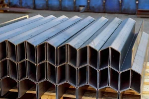
Why Use Sheet Metal?
Sheet metal is popular because it’s thin, strong, and lightweight. It offers a great balance of durability and ease of handling, making it ideal for a wide range of applications—from automotive parts to HVAC enclosures. Its thin profile allows for intricate designs and precise fabrication, while still providing the strength needed for structural parts.
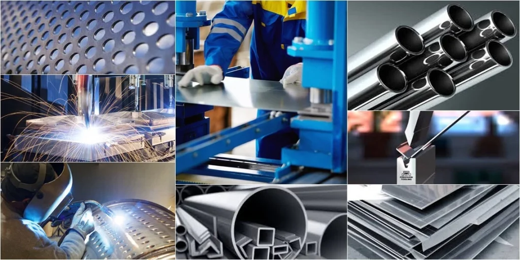
Common Sheet Metals
Here are some of the most common sheet metals used in fabrication:
- Stainless Steel: Known for its corrosion resistance and strength, perfect for outdoor or food-grade projects.
- Aluminum: Lightweight, easy to cut and form, great for aerospace and lightweight structures.
- Mild Steel: Cost-effective and strong, often used for structural components and general fabrication.
- Brass: Offers good corrosion resistance and a distinctive appearance, often used in decorative or specialty parts.
Typical Thickness Range
Most sheet metal fabrication projects use materials between 0.5 mm and 6 mm thick. Thinner sheets are easier to bend and form, while thicker sheets add strength but require more power and time to cut and shape.
Impact of Material Selection
Your choice of material influences every step of the basic sheet metal process steps:
- Cutting Methods: Some metals cut better with laser or waterjet, while others are best suited for punching or shearing.
- Forming and Bending: Thicker or harder metals may require different bend radii or more force.
- Welding: Certain materials weld more easily and produce stronger joints.
- Finishing: Surface treatments like powder coating or anodizing depend on the material’s properties.
In short, selecting the right sheet metal material sets the foundation for a smooth fabrication process and a quality final product.
Design and Preparation in the Sheet Metal Fabrication Process
Before I cut or form anything, I start with a clean digital plan. In the sheet metal fabrication process, that prep work saves time, cuts down on scrap, and helps the finished part fit the way it should.
Digital Blueprint
I usually build the part in CAD first, then export a DXF file or flat pattern for production. That gives me a clear layout for CNC sheet metal fabrication and helps keep every cut and bend consistent. If I need tight tolerances or cleaner edge control, I also match the file setup to the right CNC metal cutting process.
Design for Manufacturability
Good sheet metal design for manufacturing keeps the part simple to make. I look at a few basic rules early:
- Bend radii: I keep the bend radius realistic for the material, especially with stainless steel fabrication or aluminum sheet metal parts.
- Hole spacing: I leave enough room between holes and bends so the part does not distort.
- Flange lengths: I make sure flanges are long enough to form cleanly on the press brake.
| Design check | Why it matters |
|---|---|
| Bend radius | Helps avoid cracking and bad bends |
| Hole spacing | Reduces distortion and part rework |
| Flange length | Makes press brake fabrication more stable |
Planning Bends and Cutouts
I always plan bends and cutouts together. That matters because the sheet metal forming process can pull the material in ways that affect final fit. When I place cutouts too close to bend lines, I risk warp, cracking, or extra cleanup. Careful planning also supports better sheet metal bend radius calculation and smoother sheet metal bending later on.
Nesting for Lower Cost
Nesting is where I place multiple custom sheet metal parts on one sheet to use the metal as efficiently as possible. Better nesting means:
- less scrap
- lower material cost
- faster production
- more consistent results
For U.S. buyers who want practical turnaround and fair pricing, this step makes a real difference in the overall sheet metal fabrication process.
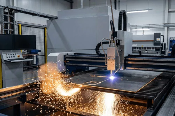
Cutting in the Basic Sheet Metal Fabrication Process
The first major step in sheet metal fabrication is turning a flat sheet into individual parts. This involves cutting the material precisely to match the design. The choice of cutting method depends on factors like material type, thickness, and desired accuracy.
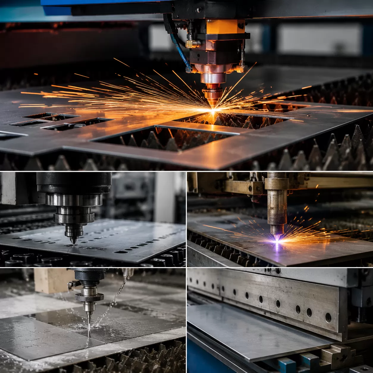
There are several common sheet metal cutting methods, including laser cutting, plasma cutting, shearing, punching, and waterjet cutting. Laser cutting is great for detailed, precise cuts on thin to medium-thick sheets, especially when tight tolerances are needed. It offers smooth edges and minimal heat-affected zones, making it ideal for complex parts. You can learn more about how laser cutting sheet metal works here.
Plasma cutting is typically used for thicker materials and faster cutting speeds but may produce rougher edges compared to laser cutting. It’s suitable for larger parts where precision isn’t as critical.
Shearing involves slicing the sheet with a straight blade, perfect for making quick, straight cuts on large sheets. It’s cost-effective but less precise, so it’s mainly used for rough sizing.
Punching uses a die to create holes or cutouts quickly and accurately, especially for repetitive features. It’s efficient for high-volume production.
Waterjet cutting uses a high-pressure jet of water mixed with abrasives to cut through thick or heat-sensitive materials without affecting the edge quality. It’s perfect when you need a clean cut on various metals without thermal distortion.
Choosing the right cutting method hinges on the material’s thickness, the required precision, and the project’s budget. Cutting accuracy and edge quality are crucial because they directly affect how well the parts will bend and fit together later. Poor edge quality can lead to issues during forming or welding, increasing rework and costs. For more on optimizing manufacturing costs, check out tips for reducing CNC machining costs.
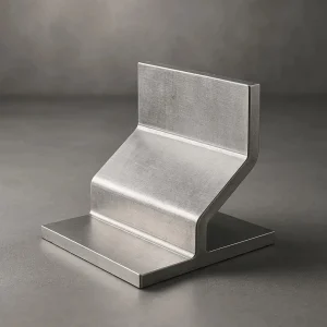
Sheet Metal Forming and Bending
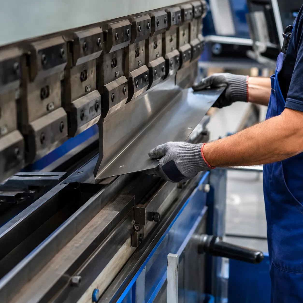
Flat sheet turns into a 3D part through the sheet metal forming process. I do not add material here; I shape what is already on the sheet. That is why sheet metal bending is such a core step in sheet metal fabrication process work, especially for custom sheet metal parts made in the U.S. market.
Press Brake Fabrication Basics
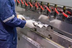
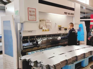
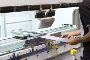
A press brake is the main tool I use for straight bends. In simple terms, it presses the sheet into a die and creates a clean angle.
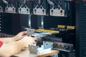
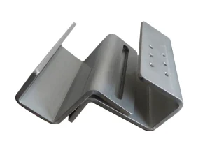
Common forming steps include:
- Bending – makes angles, flanges, and boxed shapes
- Punching – adds holes, slots, and cut features
- Stamping – forms repeated shapes fast for higher volume runs
- Embossing – raises or lowers a section without cutting it
When a part needs tight fit and clean edges, I pay close attention to the order of these steps. If I also need machined features on the same job, I may pair the part with CNC metal machining so the final fit stays consistent.
Key Bending Terms
| Term | Simple meaning |
|---|---|
| Bend allowance | Extra material needed for the bend |
| Bend radius | The inside curve of the bend |
| Springback | The metal relaxing a little after bending |
These three matter a lot in sheet metal bend radius calculation. If I ignore them, the part can end up too short, too long, or out of angle. That affects both appearance and assembly.
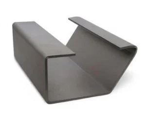
Why Forming Order Matters
I always plan the forming order before production because it affects quality and repeatability.
- Bend the part in the right sequence to avoid tool interference
- Make cutouts before bends when possible to reduce distortion
- Keep flange lengths realistic for press brake fabrication
- Leave enough space around holes and edges so the metal does not tear
- Watch springback on stainless steel fabrication and thicker material
For aluminum sheet metal parts, I usually get cleaner bends with the right radius and tooling setup. For harder metals, the bend plan has to be even more precise.
Simple Rule I Follow
If the part is difficult to bend, I stop and check:
- material type
- thickness
- bend radius
- hole spacing
- bend sequence
That small review helps me avoid rework and keeps the sheet metal assembly process smoother later on.
Joining and Finishing Sheet Metal Parts
Once the sheet metal parts are cut and formed, the next step is joining and finishing. The choice of joining method depends on the material and the specific application. Common options include MIG welding, TIG welding, spot welding, riveting, and mechanical fasteners. For example, sheet metal welding is often used for stronger, permanent joints, especially with stainless steel or aluminum. The design of the joint also plays a big role—things like hole placement, overlap, and access can influence which method works best.
After joining, finishing is key to protect the surface and improve appearance. Typical finishing processes include powder coating, anodizing, painting, and polishing. These steps help prevent corrosion and give the parts a professional look. Before finishing, it’s important to do some surface prep—debur, edge smoothing, and cleaning—to ensure the coating or polish adheres well and looks smooth.
Finally, the assembly process involves fit checks and quality inspections to make sure everything lines up and functions properly. This step is crucial for maintaining the integrity of the finished product and avoiding rework. Proper joining and finishing not only enhance durability but also help meet customer expectations for quality and appearance.


