
To an engineer or a procurement manager looking at a 3D CAD model, a finished component represents the completion of a design cycle. From the shop floor of an active production facility, however, that same part represents a sequence of physical manufacturing steps: tool geometries, material shear stresses, bend allowances, and clamping forces.
CNC fabrication is the process of shaping, cutting, and assembling raw materials using computer-controlled machinery. While the term is often associated purely with subtractive machining, industrial CNC fabrication encompasses an entire ecosystem of automated processes—including milling, turning, sheet metal laser cutting, and precision bending—working in tandem to produce a final assembly.
When outsourcing to a CNC fabrication service, production efficiency relies on how effectively a digital file translates into physical machine code. This guide outlines the core technologies, material behaviors, design rules, and quality workflows from a factory-floor perspective to assist engineering teams in optimizing production and reducing component costs.
1. Core Ecosystem Technologies in CNC Fabrication
On a production floor, projects are routed through specific departments based on the required component geometry and material type. Complex assemblies frequently utilize multiple CNC technologies sequentially.
CNC Milling and Turning (Subtractive Machining)
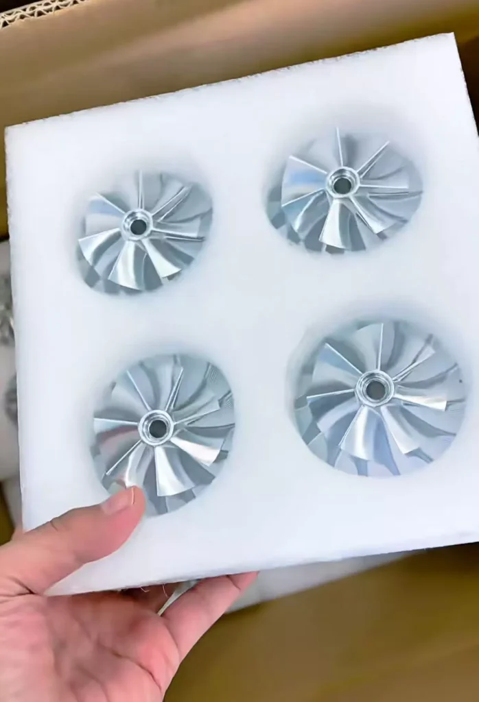
Subtractive machining removes material from a solid block or bar (known as a blank) to achieve precise three-dimensional geometries.
- CNC Milling: The raw stock remains secured in a vise or fixture while a multi-point cutting tool rotates at high speeds to carve away material. For flat, prismatic parts, 3-axis milling is the industry standard. For complex angular geometries, 5-axis milling allows the cutting tool to approach the part from any angle, enabling the machining of multiple faces in a single machine setup.
- CNC Turning: The material rotates in a chuck at high speed while a stationary single-point tool shapes the outer diameter or bores out the center. This is the primary process for shafts, bushings, and axis-symmetrical fasteners.
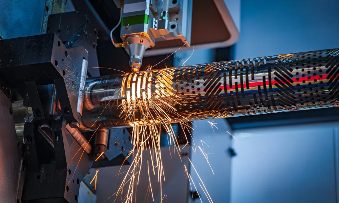
CNC Sheet Metal Fabrication (Cutting and Forming)
When designs require enclosures, chassis, brackets, or panels, the workflow utilizes sheet-based manufacturing.
- CNC Laser Cutting: High-power fiber lasers slice through flat metal sheets along programmed vector paths. This process features a minimal kerf (cut width), allowing parts to be tightly nested together to optimize material yield.
- CNC Press Brake Bending: After flat blanks are cut, they are formed using a CNC press brake. A structural punch forces the sheet metal into a matching die to create linear bends. The machine calculates the required tonnage and back-gauge positions automatically based on sheet thickness, bend radius, and material yield strength.
Factory Insight on Process Routing: Analyzing how these departments interact during the design phase can prevent unnecessary cost accumulation. For example, instead of milling a heavy electronic enclosure out of a solid aluminum block—which converts a large percentage of the raw material into waste chips—it is often more economical to fabricate the main chassis out of sheet metal and utilize CNC milling only for the precision-tolerance mounting blocks or heat sinks.
2. Material Realities: Fabricability, Stress, and Stability
A manufacturing facility evaluates raw stock based on its machinability index or formability index, which measure how easily a material can be cut or shaped without causing premature tool wear, material cracking, or internal stress deformation.
Metals: The Production Staples
- Aluminum 6061-T6: The standard baseline for CNC fabrication. It exhibits excellent cutting characteristics, bends predictably, accepts anodized coatings, and offers a favorable strength-to-weight ratio.
- Stainless Steel 304 & 316: Highly resistant to corrosion but physically demanding to machine. Stainless steel work-hardens rapidly under mechanical stress. If a cutting tool dwells too long against the material surface without cleanly shearing chips, the localized friction hardens the metal, accelerating tool breakage. It requires slower feed rates, rigid fixtures, and high-pressure flood coolant.
- Carbon Steel (CR1018 / HRA36): Highly weldable and structurally robust, making it suitable for heavy frames and structural enclosures. It requires immediate post-fabrication finishing, such as powder coating or zinc plating, to protect against surface oxidation.
Polymers: Managing Tool Pressure and Deflection
- POM (Acetal / Delrin): Highly dimensionally stable for a polymer. It holds tight engineering tolerances, cuts cleanly without significant burring, and is widely used for mechanical components such as gears, slide rails, and manifold blocks.
- Polycarbonate (PC): Offers exceptional impact resistance and optical clarity but is sensitive to localized mechanical stresses. Machining must be performed with optimized tool pathways and sharp geometries to avoid stress-induced micro-cracking around drilled holes or sharp internal corners.
| Material Class | Material | Fabrication Suitability | Primary Factory Consideration |
| Light Metals | Aluminum 6061 | High (~70% machinability) | Predictable tool wear; highly responsive to finishing. |
| Heavy Metals | Stainless 316 | Medium-Low (~35% machinability) | Work-hardens quickly; requires high torque and rigid workholding. |
| Structural Steels | Mild Steel | High (Excellent weldability) | Highly economical for structural frames; requires rust prevention. |
| Polymers | POM (Delrin) | Very High | Excellent dimensional stability; requires support to prevent thin-wall deflection. |
3. Design for Manufacturing (DFM) Principles
Incorporating Design for Manufacturing (DFM) rules directly into 3D CAD models reduces scrap rates, eliminates production bottlenecks, and lowers the overall cost per component.
Managing Inside Vertical Corners
Because CNC milling tools are round, spinning cylinders, they cannot cut a perfectly sharp inside 90-degree vertical corner.
- The Production Conflict: Specifying an absolute sharp inside corner requires slow, secondary operations such as EDM (Electrical Discharge Machining) or manual broaching, which increases cycle times.
- The Optimization: Design internal vertical corners with a radius at least 10% larger than the radius of the intended milling tool. For example, if a 6 mm end mill is assigned to clear a pocket, the internal corner radius should be designed at 3.3 mm or larger. This allows the tool to glide smoothly through the corner without experiencing sudden mechanical loading, eliminating tool chatter and improving surface finish.
Standardizing Sheet Metal Bend Radiuses
In sheet metal fabrication, every variation in bend radius requires the press brake operator to perform a physical changeover of the punch and die tooling setup.
- The Optimization: Maintain a single, uniform bend radius across the entire part design wherever possible. If a chassis uses a 2.0 mm radius on its base flanges, implementing that same 2.0 mm radius on the upper tabs allows the machine operator to complete the forming process in a single, uninterrupted machine sequence.
Applying Cost-Effective Tolerance Standards
Over-specifying tight tolerances where they are not functionally required significantly increases manufacturing costs due to slower machining feeds, specialized inspection steps, and higher rejection rates.
- The Optimization: Maintain general, non-mating dimensions at a standard commercial tolerance of ±0.125 mm. Reserve tight tolerances (±0.01 mm or finer) exclusively for critical alignment features, such as bearing bores, dowel pins, or sealing faces.
4. The Production Pipeline: From 3D Model to Verified Part
A professional CNC fabrication workflow follows a structured sequence to ensure dimensional compliance and repeatability across production lots.
[CAD Design / STEP File] ──> [DFM & Tooling Review] ──> [CAM/Nesting Programming]
                                                                  │
[Quality Metrology Lab] <── [Finishing & Coating] <── [CNC Production Execution]
Phase 1: Engineering Review and Programming
The production team imports the 3D STEP or IGES files into a CAM (Computer-Aided Manufacturing) system. For sheet metal components, parts are digitally nested onto standard sheet dimensions to optimize material usage. For machined components, software calculates the toolpaths, spindle speeds, and feed rates, outputting the data as G-code—the language that controls the motion of the CNC machinery.
Phase 2: Machine Setup and Workholding
Before production begins, the machine operator configures the physical environment:
- Workholding Calibration: Vises, custom soft jaws, modular fixtures, or laser cutting jigs are aligned to secure the raw stock against high mechanical forces.
- Tooling Verification: Cutting tools, drills, or laser cutting optics are loaded into the machine carousel. Their exact lengths and diameters are verified using automated tool setters or optical sensors.
- Work Coordinate Calibration: The operator establishes the precise coordinate origin (zero point) on the physical raw material stock using a digital touch probe.
Phase 3: Production Execution
The CNC program is executed. Machined parts generally undergo roughing passes to remove bulk material quickly, followed by finishing passes with fine-point tooling to achieve final dimensions and specified surface finishes. Sheet metal components undergo laser blanking before being moved to the press brakes for forming.
Phase 4: Deburring and Post-Finishing
Parts exiting the machines typically feature microscopic metal burrs along the cut profiles. These are removed via manual deburring, tumbling media, or vibratory bowls. Components then proceed to their specified surface finishes:
- Bead Blasting: Utilizes fine glass particles to create a uniform, non-reflective matte finish that conceals tool marks.
- Anodizing (Type II or Type III): An electrochemical process that converts an aluminum surface into a hard, corrosion-resistant oxide layer. Type III (Hardcoat) is utilized for wear-prone mechanical parts.
- Powder Coating: Applies a protective polymer layer over steel or aluminum parts to ensure long-term environmental protection.
Phase 5: Quality Control and Metrology
Critical dimensions are checked throughout the production run by operators utilizing calibrated micrometers, thread gauges, and bore gauges. For high-precision parts, components are verified within a temperature-controlled metrology lab using an automated CMM (Coordinate Measuring Machine) to scan geometries directly against the original 3D file, ensuring part compliance before packaging and shipment.
5. Engineering Data Requirements for Production
To initiate the CNC fabrication process accurately and avoid engineering delays, data hand-offs must be fully defined. A complete production package consists of two primary elements:
- 3D CAD Files (STEP or IGES format): These files provide the exact three-dimensional geometric data required by CAM software to generate toolpaths, simulate machining sequences, and program laser cutting or nesting boundaries.
- 2D Engineering Drawings (PDF format): While 3D files dictate geometry, 2D drawings convey critical manufacturing intent that cannot be extracted from a standard 3D model. This includes specific thread pitches and depths, critical dimensional tolerances (e.g., tight bearing fits), surface roughness requirements (such as Ra ≤ 1.6 µm), and localized post-processing or masking instructions.
Ensuring alignment between the 3D model and 2D drawing establishes a reliable, non-ambiguous baseline for production execution, inspection verification, and component repeatability.