
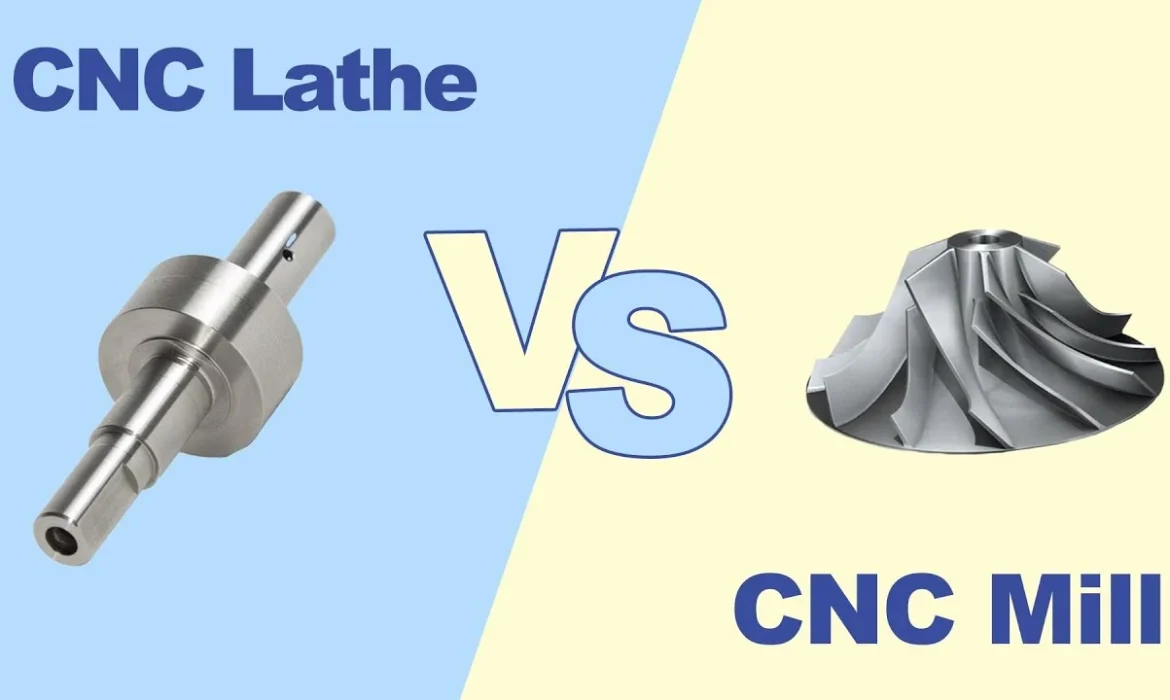
Instead of defaulting to a standard milling setup for every new design, it is more efficient to evaluate the performance of CNC Lathe Machining versus milling based on the part’s geometric features. This approach helps find the optimal balance between cycle time and precision. Understanding the technical tipping points between these two processes is the most direct way to ensure production efficiency and realistic unit pricing.
1. The Practical Logic of Symmetry and Surface Finish
The most intuitive factor in process selection is the axis of symmetry. In CNC Lathe Turning, the workpiece rotates while the cutting tool remains stationary. For any feature concentric to the centerline, this method offers a significantly higher Material Removal Rate (MRR) compared to milling.
If a part requires tight concentricity (e.g., ±0.01mm) between multiple diameters, a lathe handles this naturally because the workpiece does not need to be repositioned during the entire machining process. On a mill, achieving the same alignment typically requires specialized rotary fixtures or multiple setups—each of which introduces a potential margin for error. Furthermore, for components requiring high-quality seals (such as O-ring grooves or bearing seats), the continuous helical path of CNC turning provides a superior surface finish (Ra) compared to the interrupted cuts of a milling tool.
2. When Precision Demands a Precision Automatic Lathe (Swiss-Type)
As part sizes shrink or length-to-diameter ratios increase, standard machining often hits a bottleneck. At this stage, choosing a Precision Automatic Lathe (commonly known as a Swiss-Type machine) becomes the logical choice over traditional mills or standard lathes.
In standard CNC turning, the workpiece is held at one end. If the part is slender, the cutting pressure can cause material deflection and “chatter.” A precision automatic lathe solves this by using a guide bushing to support the workpiece directly at the point of the cut. For engineers designing thin shafts for robotics or precision pins for medical devices, this setup allows for maintaining tolerances as tight as ±0.005mm in a single pass. By leveraging these specific parts of a CNC Lathe, secondary operations that would otherwise be mandatory on a milling center can often be eliminated.
3. In-Depth Analysis: Material Behavior in Turning vs. Milling
The choice between a lathe and a mill often depends on how a specific material reacts to thermal stress and mechanical strain. In the current manufacturing landscape, understanding these nuances is critical for maintaining dimensional stability.
Superalloys and Titanium (The Thermal Factor)
Materials like Titanium (Grade 5 / Ti-6Al-4V) and Inconel 718 are known for their low thermal conductivity.
- In Milling: The tool teeth constantly impact the material, creating rapid heating and cooling cycles. This thermal shock often leads to micro-cracking at the tool edge and inconsistent surface integrity.
- In CNC Machining: Turning allows for “constant cutting.” By utilizing Constant Surface Speed (CSS), the tool maintains stable contact with the workpiece, allowing heat to be carried away consistently by the chips rather than soaking into the part. For critical aerospace components, this stability determines whether a part holds its tolerance or warps due to internal stress.
Stainless Steel and Work-Hardening
Stainless steels, particularly 304 and 316L, are prone to work-hardening—a phenomenon where the material becomes harder and more brittle as it is deformed by the tool.
- Milling Risk: If a milling cutter “rubs” even slightly before cutting, it creates a hardened layer that the next tooth must struggle to penetrate, leading to rapid tool failure.
- Turning Advantage: In CNC turning, we can maintain a heavy, consistent feed rate. The tool stays “under” the hardened layer created by the previous revolution, ensuring a cleaner cut and more predictable surface roughness (Ra).
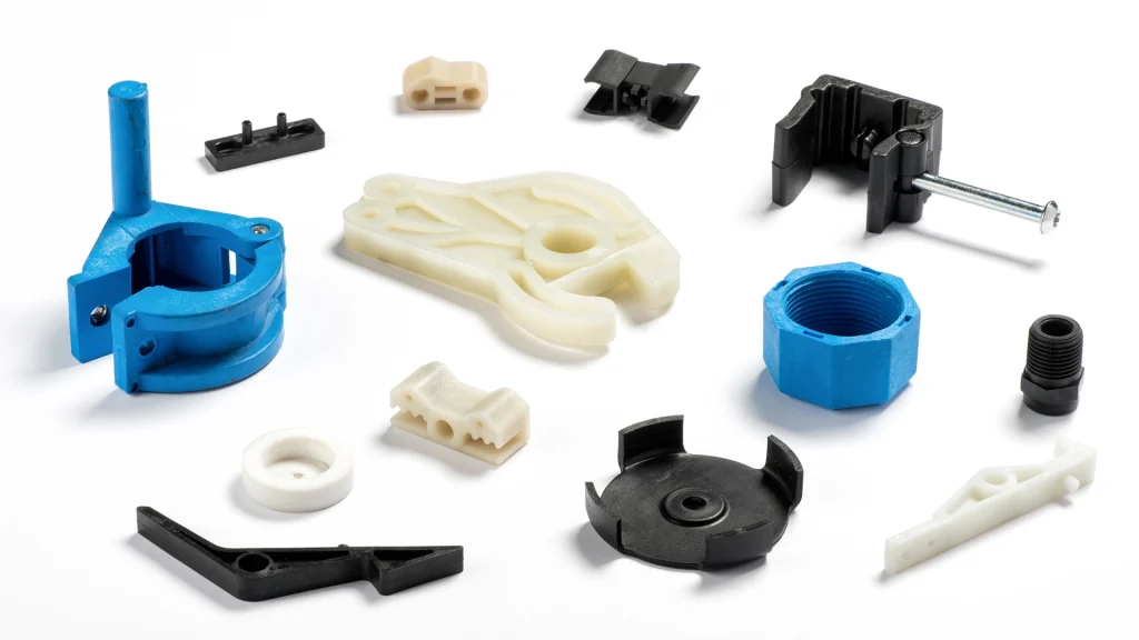
Engineering Plastics (PEEK, Delrin, and PTFE)
For medical and food-grade applications, polymers like PEEK and POM (Delrin) have high thermal expansion coefficients and easily deform under the clamping pressure of a milling vise.
- Stress Distribution: In a precision automatic lathe, centrifugal forces are distributed symmetrically around the part’s axis. This radial symmetry helps maintain the “roundness” of thin-walled tubes.
- Surface Smearing: Milling large flat areas on plastic often leads to “smearing” due to heat buildup at the tool tip. The single-point cutting action of a lathe, combined with specialized sharp-edged inserts, produces much crisper features and tighter tolerances on plastic diameters.
4. Economics: Setup Cost vs. Run Time
Total project cost is essentially a tug-of-war between initial setup fees and actual running time.
- Milling: Often involves complex workholding—such as vises, custom jigs, or “soft jaws.” These require significant alignment and verification time, which increases the “setup” or “startup” costs on a quote.
- CNC Machining: Generally utilizes standard three-jaw chucks or collet systems. Setup is faster, and toolpaths are typically simpler.
For mid-to-small batches of 100 to 500 pieces, the reduced setup time of CNC turning can lower the total cost by 15–20%, even if the part has small milled features that require Live Tooling.
5. DFM: Optimizing Design for Production
To maximize the advantages of the CNC Lathe vs. Mill decision, we recommend several Design-for-Manufacturing (DFM) adjustments:
- Standardize Radii: Internal corners in turning are formed by the tool’s nose radius. Avoid specifying perfectly sharp internal corners; a radius of 0.2mm to 0.4mm is standard and easier to produce.
- Monitor the Aspect Ratio: Unless using a precision automatic lathe, try to keep the length-to-diameter ratio below 4:1 to minimize vibration and ensure consistent diameter from end to end.
- Consolidate Features: If a round part requires a hex flat or a cross-drilled hole, check if your supplier has lathes with “Live Tooling.” This allows the part to be finished in one operation, eliminating the cost of a secondary milling setup.
6. Decision Matrix
| Question / Feature | Recommended Process |
|---|---|
| Is the part primarily cylindrical? | CNC Lathe Machining |
| Are there tight tolerances on concentricity or runout? | CNC Turning |
| Is the part under 32mm with a high L:D ratio? | Precision Automatic Lathe (Swiss) |
| Does the part have large flat surfaces or non-symmetrical pockets? | CNC Milling |


