
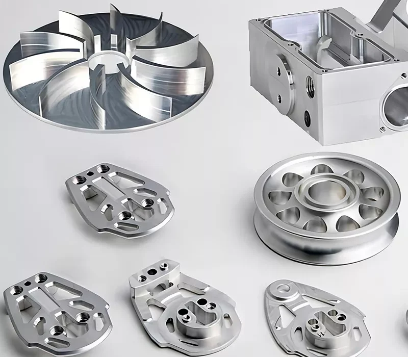
Many of the mission-critical technologies we rely on daily—from the complex, lightweight blisks inside an aerospace turbine and the mirror-finish curvature of a titanium medical implant to the thin-walled aluminum chassis protecting 5G base station electronics—depend entirely on CNC milling.
Let’s skip the marketing fluff and look at the shop floor reality. Think of it like a seasoned machinist chatting at a cafe: manual milling is a fine art that relies entirely on a veteran operator’s muscle memory. If your hand slips on the handwheel by a fraction of a millimeter on the final pass, you don’t just lose time—you scrap an expensive block of raw stock. Modern CNC milling removes that human variability. By integrating rigid machine frames with high-speed processing and advanced control algorithms, it turns complex blueprints into flawless physical parts.
However, a CNC mill is only as smart as the program you feed it. If your 3D model ignores the physical realities of rotating cutting tools, your production costs will skyrocket. This comprehensive guide moves beyond basic definitions. We will break down the closed-loop manufacturing process, analyze multi-axis machine configurations, and share hard Design for Manufacturing (DFM) rules so you can bypass costly manufacturing bottlenecks and optimize your component costs.
2. What Is CNC Milling & How It Works
CNC milling is an automated subtractive manufacturing process where a computer-controlled rotating cutting tool selectively removes material from a stationary or multi-axis workpiece to produce a highly accurate custom part.
Unlike additive manufacturing (such as industrial 3D printing) which builds components layer by layer, CNC milling carves out features from a solid blank. The industrial operational lifecycle consists of a closed-loop, five-step pipeline:
Every part begins as a digital twin in Computer-Aided Design (CAD) software. Hardware engineers model the component’s geometry, defining nominal dimensions and specific geometric tolerances. Successful design at this stage requires a strict adherence to engineering logic rather than raw aesthetics.
The 3D model is imported into Computer-Aided Manufacturing (CAM) software, where a manufacturing engineer assigns specific cutting tools to various features. The CAM software converts this geometry into G-code (Geometric Code)—the standardized programming language that dictates absolute coordinate movements, spindle speeds, and feed rates. Modern premium CAM processors utilize advanced control algorithms for tool path optimisation, eliminating unnecessary air-cutting movements to shave critical seconds off the cycle time.
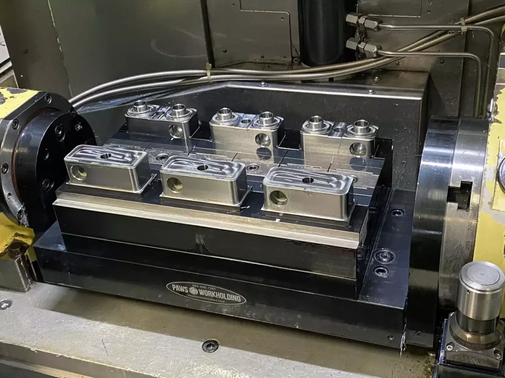
Before the spindle spins, the machine operator configures the physical workspace. The raw stock is secured to the worktable using rigid workholding fixtures (such as hydraulic vises, custom jigs, or modular clamps) to counteract the immense cutting forces. The operator then loads the correct cutting tools into the tool carousel, sets tool length offsets, and calibrates the work coordinate system (WCS) origin.
Once the setup is verified, the operator runs the program. The machine head or worktable executes the G-code lines with micro-inch repeatability. The machine spindle drives the cutting tool at several thousand RPM, achieving high-speed processing. Simultaneously, flood coolant or pressurized mist is directed at the cutting zone to dissipate thermal heat, lubricate the cut, and evacuate chips to prevent recutting.
After the machining cycle concludes, the raw part is separated from the stock material. Depending on the final application, the part moves to optional finishing stages. This can range from simple structural deburring and bead blasting to functional chemical treatments like Type II or Type III hardcoat anodising, passivation, or electroplating.
3. CNC Milling Machine Types & Operations
CNC mills are primarily categorized by their axis mobility and cutting tool orientation found on modern shop floors.
The Axis Matrix: 3-Axis vs. 5-Axis Machining
- 3-Axis CNC Milling: The traditional standard of the machine shop. The cutting tool moves along the linear Cartesian coordinate system: X-axis (sideways), Y-axis (back and forth), and Z-axis (up and down), while the workpiece remains clamped in place. It is highly cost-effective for simpler, prismatic geometries but requires manual re-fixturing if you need to machine features on multiple sides of the part.
- 4-Axis CNC Milling: Adds a rotational axis (typically the A-axis around the X linear path), allowing the workpiece to rotate. This enables continuous indexing and pocketing on cylindrical or curved surfaces without breaking setup.
- 5-Axis CNC Machining: The gold standard for complex geometries. A 5-axis machine adds two rotational axes (A, B, or C depending on whether it is a trunnion or swivel-head configuration). This permits the cutting tool to remain perpendicular to complex, sculpted surfaces continuously. By completing the component in a single, unified setup, 5-axis milling eliminates setup-induced cumulative tolerances, drastically improving precision and ensuring a superior surface finish.
Core Milling Operations
To achieve specific geometric features, machinists deploy distinct cutting methodologies:
| Milling Operation | Tool Orientation & Action | Best Suited For |
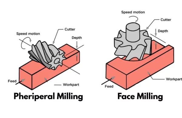
| Face Milling | The tool’s rotational axis is perpendicular to the workpiece surface. It cuts using teeth on its flat tip and outer face. | Generating exceptionally flat surfaces with minimal roughness values (Ra). |
| Plain Milling | The tool’s rotational axis is parallel to the target surface. The cutter features peripheral teeth along its cylindrical body. | Mass material removal, carving deep side steps, or cutting broad rectangular slots. |
| Angular Milling | The cutting tool’s axis of rotation is oriented at a specific non-perpendicular angle relative to the work surface. | Milling precise chamfers, dovetail slides, v-grooves, and angular structural bevels. |
| Form Milling | Uses custom-ground, non-cylindrical cutters that match a specific, inverted geometric profile. | Producing intricate curved channels, hemispherical pockets, and highly specialized gear teeth. |
4. DFM Rules & Tolerances for CNC Milling
If you want your design to be clear and actionable, you must back it up with hard numbers. This section details the core DFM metrics that separate a theoretical design from an efficient production run.
Standard Tolerance Benchmarks
CNC machining centers can hit tight tolerances, but precision carries a price tag. Slower feed rates, specialized sub-micron tooling, and regular in-process inspection all extend machine time and increase costs.
| Process Configuration | Standard Linear Tolerance | High-Precision Custom Tolerance |
| Standard 3-Axis Milling | ±0.13 mm (±0.005”) | ±0.025 mm (±0.001”) |
| Advanced 5-Axis Milling | ±0.13 mm (±0.005”) | ±0.010 mm (±0.0004”) |
| Engraving / Detailing | ±0.13 mm (±0.005”) | ±0.050 mm (±0.002”) |
⚠️ Cost Driver Warning: Machining costs scale exponentially as tolerances tighten. Unless a feature interfaces directly with a press-fit bearing or high-pressure seal, maintain a standard linear tolerance of ±0.13 mm to keep cycle times and scrap rates low.
Four Critical DFM Red Lines
- Avoid Curved Holes: A standard drill bit or end mill cannot bend around corners. If your part requires internal paths for fluid routing or conformal cooling, you must either split the part into an assembly or pivot to metal 3D printing.
- Design Internal Corners with Radii: Because milling cutters are circular, they cannot cut a perfectly sharp internal 90° vertical corner. They will always leave a radius equal to the radius of the tool. Always specify an internal fillet radius that is at least 10% larger than the tool radius. This allows the cutting tool to sweep through the corner smoothly instead of stopping and turning sharply, eliminating severe tool chatter and potential tool breakage.
- Avoid Excessively Thin, High Walls: The vibrational forces during high-speed processing will cause thin, elevated walls to flex. For metals, keep wall thicknesses above 0.8 mm; for plastics, stay above 1.5 mm. Thin walls suffer from dimensional drift and poor surface finish.
- Limit Blind Hole Depth-to-Diameter Ratios: Deep, narrow cavities present a severe risk of tool deflection. Furthermore, evacuating chips from a deep blind hole is highly difficult. If chips cannot escape, they are recut by the tool, damaging the internal surface finish and potentially causing catastrophic tool failure. Limit pocket depths to 4x the tool diameter whenever possible.
5. Material Selection Guide: Metals vs. Plastics
Material choice directly dictates a component’s structural weight, environmental resilience, and overall machinability—the ease with which a tool can shave away material without inducing premature tool wear.
| Material Class | Material Name | Machinability Rating | Primary Manufacturing Applications |
| Metals | Aluminum 6061-T6 | Excellent | Aerospace bulkheads, automotive brackets, and consumer electronics casings. Accepts anodizing beautifully. |
| Stainless Steel 316 | Moderate to Poor | Marine hardware, medical surgical instruments, and chemical processing valves. Highly corrosion-resistant. | |
| Titanium (Grade 5) | Poor | Aerospace structural links and medical orthopedic implants. Exceptional strength-to-weight ratio. | |
| Copper (C101/C110) | Fair | Electrical busbars, high-performance heat sinks, and thermal management components. | |
| Plastics | POM (Delrin/Acetal) | Excellent | Precision gear wheels, industrial bushings, fuel system components, and electrical insulators. |
| PEEK | Good | High-temperature aerospace seals, downhole oil & gas components, and medical implants. | |
| Nylon (PA6 / PA66) | Good | Heavy-duty wear pads, structural rollers, and generic engineering prototypes. | |
| Acrylic (PMMA) | Fair | Optical manifolds, transparent fluid sight glasses, and premium display cases. |
6. Pros, Limitations, & Alternatives
We must look objectively at where CNC milling excels and where it falls short compared to alternative manufacturing methods.
Advantages (The Benefits)
- Isotropic Material Integrity: Unlike 3D printing, which creates structural parts layer by layer, CNC milling carves parts from solid extruded or forged stock. This ensures uniform mechanical strength and load-bearing performance across all three dimensions.
- Extreme Repeatability: Computer-controlled execution removes human error, ensuring that part number 1,000 matches part number 1 down to the micron.
- Unrivaled Material Versatility: If a material can be procured in a solid block, it can generally be milled—whether it’s soft structural foam or ultra-hard aerospace superalloys like Inconel.
Disadvantages (The Limitations)
- Substantial Setup Costs: The engineering hours required to generate CAM toolpaths, build custom workholding fixtures, and configure the machine make low-volume prototyping expensive on a per-part basis compared to additive methods.
- Material Inefficiency: Because it is a subtractive methodology, a significant percentage of the initial raw material block is reduced to scrap chips, increasing raw material overhead.
Cross-Process Technology Matrix
- For 1 to 50 complex plastic prototypes: Additive manufacturing (3D printing) is often faster and more cost-effective because it bypasses initial tooling setups.
- For 10,000+ plastic components: Injection molding offers a much lower per-part cost once you amortize the high upfront cost of the steel molds.
- From a single prototype up to mid-volume production batches (up to 5,000 parts), CNC milling remains the most dependable solution. If your project involves complex turned components or symmetrical cylindrical geometries alongside milled features, our specialized custom cnc machining service provides seamless multi-tasking capabilities to handle complex print requirements under one roof.
7. The Business Logic: Why Outsourcing Makes Sense
Running an internal machine shop requires a significant amount of capital expenditure. To match the precision of advanced machining centers, an organization must absorb massive fixed costs:
- Investing in high-end multi-axis machine tools (like a premium 5-axis vertical machining center or a high-speed compact drilling center).
- Paying annual licensing fees for advanced CAM software and specialized post-processors.
- Retaining experienced CNC programmers and operators who understand advanced tool path optimisation and complex workholding strategies.
Outsourcing your production to an established manufacturing partner shifts this fixed capital risk into a flexible operating expense. A specialized shop optimizes its machine uptime by nesting multiple customer orders across shared production schedules, lowering your individual unit cost. Furthermore, a dedicated team provides immediate DFM feedback during quoting, helping you catch design errors before chips fly and ensuring your parts are machined right the first time.
8. Conclusion & CTA
In modern manufacturing, CNC milling bridges the gap between digital precision and physical durability. By understanding axis configurations, respecting DFM constraints like internal corner radii, and matching your design intent with the right material, you can maximize your component’s performance while keeping production costs low.
Don’t let an optimized CAD model get stuck in a prolonged quoting cycle.
Take advantage of our automated digital manufacturing workflow. Upload your 3D CAD files (STEP, IGES, or Parasolid formats) to our secure online portal today. Our engineering team will analyze your geometry and deliver a comprehensive DFM manufacturability analysis alongside an accurate, instant quote within hours. Let’s turn your engineering blueprints into high-precision reality.