
The “Silent Quote” Trap: Analyzing the Initial Response
Sourcing CNC Machining of Complex Parts is often a minefield. You send out a STEP file and a PDF drawing, you get a price, and you hope for the best. But in my experience at MS Machining, the failure usually happens long before the first chip is cut—it happens in the initial email thread. The way a machine shop responds to your Request for Quote (RFQ) is the single biggest indicator of whether your parts will arrive on spec or end up in the scrap bin.
When we receive a complex print, we don’t just look at the overall dimensions; we look for the traps. If a shop sends you a quote without asking a single clarifying question, that is the “Silent Quote” trap. Silence suggests they either didn’t review the engineering nuances or they plan to “figure it out later,” which usually translates to delays and non-conformance.
The “Yes-Man” Red Flag: Fast Quotes vs. Accurate Quotes
We all want speed, but instant gratification is dangerous in precision CNC milling. There is a massive difference between an automated quote and an engineered quote.
- The “Yes-Man” Shop: Returns a quote in 30 minutes for a 5-axis manifold. They say “Yes” to every tolerance and “Yes” to your 3-day lead time. This is a red flag. They are likely using an algorithm that calculates material volume and runtime but ignores fixture complexity or tool access.
- The Accurate Partner: Takes the time to analyze the geometry. If I look at a part and see a feature that requires a custom form tool or a risky setup, I’m going to flag it.
If a potential supplier accepts a highly complex design without pushing back on anything, they likely haven’t identified the risks yet. You want a partner who says, “We can do this, but here is the risk,” not someone who blindly accepts the order.
Inquiring About Critical Tolerances and Surface Finish
Tight tolerance machining requires specific conversations. A generic “ISO 2768-m” callout is fine for general features, but complex parts often have critical fits that require tighter control. When evaluating a shop, specifically ask how they plan to achieve your hardest requirements.
Watch for these responses:
- Vague: “We have high-precision machines.” (Means nothing).
- Specific: “We will rough this feature on the mill and finish it with wire EDM to hold the +/- 0.005mm tolerance.” (This proves they have a plan).
Surface finish is another failure point. Achieving a 0.8 Ra (32 micro-inch) finish on a flat face is easy; achieving it on a 3D contoured surface inside a deep pocket is a different beast. We always verify if the customer needs that finish for sealing (function) or just aesthetics, as this dictates the machining strategy.
Validating GD&T Understanding
Many shops claim to understand Geometric Dimensioning and Tolerancing (GD&T), but few apply it correctly during inspection. A shop might hit the linear dimensions but fail the True Position or Profile tolerances because they don’t understand datums.
To validate a shop’s capability, ask a specific question about a Feature Control Frame on your drawing. For example:
- “How will you fixture this part to satisfy Datum A and Datum B simultaneously?”
- “Do you have the probing capability to verify this profile tolerance in-process?”
If they can’t explain the setup strategy relative to your datums, they are guessing.
Material Certifications and Traceability Checks
Never assume the metal is what they say it is. In the world of custom metal fabrication, material mix-ups are a silent killer. For critical aerospace or medical components, material traceability is non-negotiable.
Your checklist for material validation should include:
- Mill Test Reports (MTRs): Ensure the shop can provide physical, chemical, and mechanical properties from the material mill.
- Heat Lot Traceability: Can they trace the specific part back to the raw bar stock heat lot?
- ISO 9001 Standards: An ISO 9001 certified machine shop will have established procedures for segregating materials to prevent cross-contamination (e.g., keeping aluminum chips away from titanium).
We treat material verification as the foundation of quality. If the raw material is wrong, the most precise machining in the world won’t save the part.
Assessing Design for Manufacturability (DFM) Feedback
When you are outsourcing CNC machining of complex parts, the feedback you receive on your CAD model is the first real test of a supplier’s competence. If a shop accepts a complicated design without asking a single question, that is not efficiency; it is a warning sign.
Using DFM as a Diagnostic Tool
A generic “quote received” email doesn’t cut it for high-precision work. You want a partner who performs a thorough Design for Manufacturability (DFM) review. This feedback loop is where we catch potential failures before metal is ever cut. If I see a design that is going to fail or cost double what it should, I speak up. If your potential supplier stays silent on obvious issues, they are likely just pushing buttons rather than engineering solutions. While everyone wants fast CNC machining results, skipping this diagnostic phase guarantees delays on the backend.
Identifying Sharp Internal Corners and Radius Issues
One of the most common “gotchas” in precision CNC milling involves internal geometry. Since standard CNC milling machines utilize rotating round cutters, creating a perfectly sharp internal corner is physically impossible without specialized processes like EDM.
If your design has square internal corners and the shop doesn’t flag them, you are heading for trouble. A competent machinist will suggest adding a corner radius (fillet) or using a “dog-bone” relief. Ignoring this leads to excessive tool deflection and chatter, resulting in poor surface finishes and out-of-tolerance parts.
Deep Pockets and Depth-to-Diameter Ratios
Deep cavities are another major failure point. The physics of machining dictate that as a tool gets longer and thinner, it becomes less stable.
- The Golden Ratio: We generally look for a depth-to-diameter ratio of 3:1 or less.
- The Risk: Anything deeper requires specialized tooling or multi-axis strategies to avoid vibration.
- The Check: If you have a 10mm deep pocket that is only 1mm wide, and the shop doesn’t warn you about the risk of tool breakage or tapered walls, they aren’t paying attention.
Evaluating Workholding Strategies for Non-Prismatic Shapes
Holding a square block is easy; holding a complex, organic shape is an art. Custom metal fabrication risks skyrocket when a part cannot be easily clamped in a standard vise. Ask your supplier how they plan to fixture the part.
- Soft Jaws: Are they machining custom jaws to match the part profile?
- Vacuum Fixtures: Are they using vacuum plates for thin, flat parts to prevent warping?
- Tabs: Will they leave tabs that need to be removed manually later?
If they cannot explain their workholding strategy, they likely haven’t thought about how to keep your part stable under the cutting forces.
Evaluating Technical Hardware & Software Capabilities

When vetting a partner for CNC Machining of Complex Parts, the equipment list tells a story. I don’t just look for brand names; I look for the right configuration for the job. If a shop tries to force a complex aerospace geometry onto a standard 3-axis mill, they are introducing unnecessary risk. You need to verify that their hardware matches the complexity of your design to avoid costly scraps and delays.
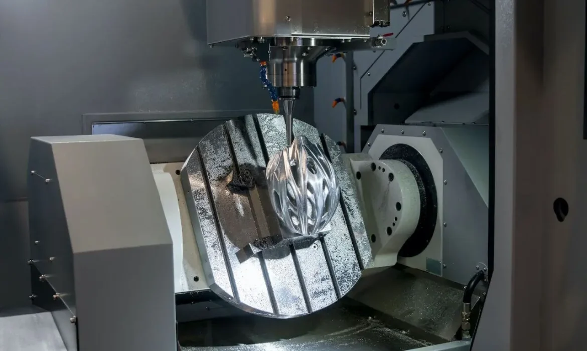
3-Axis vs. 5-Axis Machining for Complex Geometries
For simple prismatic parts, 3-axis machines are fine. But when we are dealing with compound angles, undercuts, or organic surfaces, relying on 3-axis equipment often leads to failure. This approach requires operators to manually flip and re-fixture the part multiple times. Every time a human touches the part to reposition it, accuracy drops.
I prioritize shops that offer 5-axis CNC machining services. This technology allows the cutting tool to approach the workpiece from virtually any direction. It handles complex contours in a single setup, ensuring that the geometric relationship between features is maintained perfectly.
Reducing Stack-up Errors with Multi-Axis Setups
The silent killer in precision manufacturing is tolerance stack-up. If a shop uses multiple fixtures to machine different sides of a part, the small error in each fixture adds up. By the time the part is finished, the total error often exceeds the allowable tolerance.
Multi-axis machining capabilities solve this by keeping the workpiece stationary. This significantly reduces cumulative error. If you are wondering how accurate CNC milling is when comparing single-setup versus multi-setup processes, the difference is often what separates a usable part from a paperweight.
CAM Software Proficiency and Collision Avoidance
High-end machines are useless without the software to drive them. Complex geometries require advanced CAM (Computer-Aided Manufacturing) strategies to manage tool paths efficiently. I always check if the shop uses simulation software to detect collisions before the machine starts running.
If they aren’t simulating the cut, they are guessing. Proper simulation prevents tool gouging and machine crashes, which ensures your CNC precision parts, fabrication schedule stays on track.
Hardware Selection Guide:
| Feature | 3-Axis Machining | 5-Axis Machining |
|---|---|---|
| Ideal For | Flat surfaces, simple holes | Complex curves, impellers, turbines |
| Setups Required | Multiple (High risk of error) | Single (High precision) |
| Surface Finish | Good on flat areas | Superior on contoured surfaces |
| Cost Efficiency | Lower for simple parts | Higher value for complex parts |
The Quality Control (QC) Litmus Test
When dealing with CNC Machining of Complex Parts, the quality control room tells you much more than the sales pitch ever will. If a shop thinks a standard pair of calipers is enough to verify a turbine blade or a complex medical housing, you are heading for trouble. QC isn’t just about checking the final box; it is the only thing standing between a functional component and an expensive paperweight.
Why Standard Hand Tools Fail on Complex Contours
Calipers and micrometers are fantastic for checking simple lengths, widths, and thicknesses on square blocks. However, they are practically useless for organic shapes, lofted surfaces, or complex curves. If your design involves 3D surfacing, standard hand tools cannot verify if the physical profile matches the CAD model. You need a partner offering custom CNC machining services that utilizes advanced metrology equipment to capture those non-linear dimensions accurately. Relying on hand tools for complex contours introduces massive human error and often results in parts that look right but don’t fit.
Necessity of CMM Verification for GD&T
This is where Coordinate Measuring Machine (CMM) inspection becomes non-negotiable. Complex geometries often come with strict Geometric Dimensioning and Tolerancing (GD&T) requirements that go beyond simple linear measurements. You cannot eyeball these features.
- Profile of a Surface: A CMM traces the exact contour to ensure it stays within the tolerance zone defined by the CAD data.
- True Position: Verifies hole locations relative to datums, ensuring proper alignment during assembly.
- Flatness & Parallelism: Essential for sealing surfaces that calipers cannot measure across a complete part face.
In-Process Inspection vs. Final Inspection
Waiting until the part is finished to check for errors is a waste of time and material. Reliable metal parts fabrication requires in-process inspection. This means using on-machine probes or stopping the machine to measure critical features before the setup is broken down.
If a shop only inspects at the very end, they are gambling with your lead time. If a bore is undersized while the part is still clamped, it can be fixed in minutes. If it’s caught during final inspection, the part is often scrap.
The Role of First Article Inspection (FAI)
Never approve a full production run without a First Article Inspection (FAI) report. This is your “golden sample.” It proves that the manufacturing process is capable of producing parts to spec before the machine runs hundreds of units. An ISO 9001 certified machine shop will provide a detailed FAI report mapping every dimension on your print to the actual measurement of the first part off the line. If a supplier hesitates to provide this data, it is a major red flag that they lack confidence in their own process stability.
Material & Surface Treatment Risks
When dealing with CNC Machining of Complex Parts, the metal itself is often the biggest variable. It isn’t just about cutting shapes; it’s about predicting how the material reacts to being cut and how surface treatments affect the final dimensions. If a shop doesn’t have a plan for material behavior, you are looking at a high risk of failure.
Material Stress Relief and Warping Risks
One of the most overlooked custom metal fabrication risks is internal residual stress. When we remove large amounts of stock from a block of aluminum or steel to create a complex geometry, we release forces trapped inside the material. The result? The part might warp, twist, or bow the moment it is unclamped from the fixture.
A competent shop anticipates this. For high-precision work, we often employ a specific workflow:
- Roughing: Remove the bulk of the material.
- Stress Relief: Allow the part to settle (sometimes using heat treatment).
- Finishing: Machine the final dimensions after the movement has stabilized.
If your supplier isn’t discussing stress relief for thin-walled or asymmetrical parts, ask them why. Reliable precision CNC machining services understand that maintaining geometric integrity requires managing these internal forces, not just ignoring them.
Managing Post-Processing Consistency and Tolerance Stacking
Post-processing is where many “perfect” parts fail inspection. Treatments like anodizing, plating, or powder coating add thickness to the surface. If the machinist cuts the part to the final print dimension before coating, the added layer will push the part out of tolerance. This is known as tolerance stacking.
To ensure CNC production quality control, we must machine the part to a “pre-plate” dimension that accounts for the coating build-up. Additionally, surface finish requirements (Ra) must be met before any treatment is applied, as coatings will often highlight, rather than hide, tool marks.
Key questions to ask regarding post-processing:
- Buildup Accounting: Does the CAM program account for the thickness of the plating (e.g., Type III Hardcoat Anodize adds ~0.002″)?
- Masking Precision: How does the shop handle masking for threaded holes or critical grounding surfaces?
- Batch Consistency: Can they guarantee color and thickness consistency across different production batches?
FAQ: Common Concerns When Outsourcing Complex CNC Parts
Outsourcing CNC precision parts with intricate geometries can feel like a gamble if you don’t know what to look for. Here are the straight answers to the most common questions we get from clients navigating the US market.
How do I know if a shop can handle tight tolerances?
Don’t just take a “yes” for an answer. You need to validate their equipment and processes. A shop capable of tight tolerance machining (±0.0005″ or better) must have a climate-controlled environment and advanced metrology gear.
- Check for CMMs: If they don’t have a Coordinate Measuring Machine (CMM), they cannot reliably verify complex GD&T.
- Ask for Certifications: An ISO 9001 certified machine shop has standardized processes that reduce variability.
- Review Past Work: Ask for case studies similar to your design. Top-tier CNC precision machining services will happily provide data proving their capability to hold critical dimensions.
What is the standard lead time for complex machined parts?
For complex CNC prototyping complex parts, the typical lead time in the US is 2 to 4 weeks.
- Week 1: Material procurement and CAM programming.
- Week 2-3: Machining and processing.
- Week 4: QC inspection and finishing.
If a shop promises a 3-day turnaround on a highly complex manifold without a significant rush fee, be cautious. Speed often comes at the cost of the First Article Inspection (FAI) report accuracy.
Why is 5-axis machining better for complex parts?
It comes down to reducing “stack-up” errors. In standard 3-axis machining, the operator has to manually flip the part to machine different sides. Every time the part is moved, you lose a tiny bit of accuracy.
5-axis CNC machining services allow the cutting tool to access five sides of the workpiece in a single setup. This ensures that features on different sides of the part are perfectly aligned, drastically reducing rejection rates for complex geometries.
How does material selection affect machining failure rates?
Material dictates the machining strategy. Choosing the wrong material for the geometry is a common cause of failure.
- Hard Metals (Titanium, Inconel): High risk of tool deflection and chatter, which ruins surface finish and dimensions.
- Soft Metals (Copper, Aluminum): High risk of gummy chips clogging tools or the part warping due to internal stress release.
We always review the material choice during the Design for Manufacturability (DFM) review to ensure it aligns with the required tolerances and budget.