
Metal Fabrication Process: Complete Guide to Custom Metal Manufacturing
Overview of the Metal Fabrication Process
Metal fabrication is a manufacturing process that involves transforming raw metal materials into finished components through a series of operations. The process typically begins with engineering design and material preparation, followed by cutting, forming, machining, welding, surface treatment, assembly, and quality inspection. Each stage plays an important role in achieving the required dimensions, strength, appearance, and performance of the final product.
Design → Material → Cutting → Forming → Machining → Welding → Surface Finishing → Assembly → Inspection → Packaging
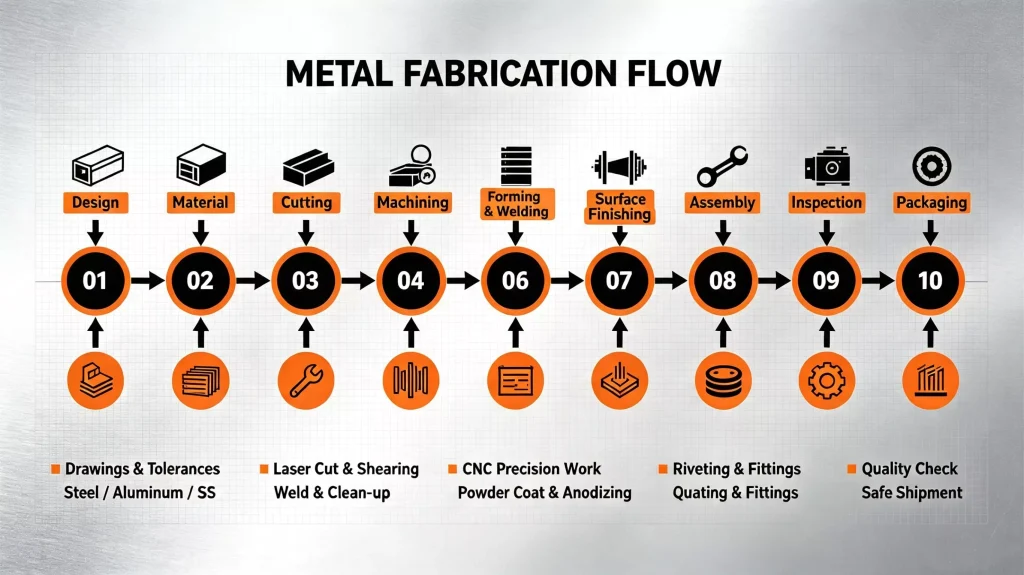
Step 1. Engineering Design & Pre-Fabrication Preparation
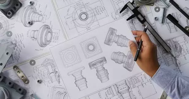
Engineering Drawing & CAD Design
Engineering drawing and CAD design define the technical requirements and manufacturing specifications for a metal fabrication project. This stage involves creating detailed 2D fabrication drawings and 3D CAD models that specify part geometry, dimensions, material requirements, tolerances, surface finishes, and assembly details.
CAD models are used to verify design accuracy, evaluate manufacturability, and identify potential issues before fabrication begins. The completed drawings provide the necessary references for subsequent processes, including cutting, forming, CNC machining, welding, and assembly, ensuring that components are produced according to the defined specifications.
Material Selection
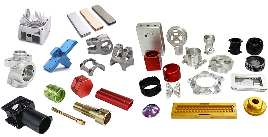
Material selection is an important step in the metal fabrication process, as the chosen material directly affects the component’s strength, durability, corrosion resistance, weight, and manufacturing requirements. The selection is typically based on factors such as mechanical properties, operating environment, design specifications, fabrication methods, and cost considerations.
Common sheet metal materials used in fabrication include Cold Rolled Steel (CRS), Hot Rolled Steel (HRS), Stainless Steel 304, Stainless Steel 316, Aluminum, Brass, and Copper. Each material offers different characteristics for specific applications. For example, stainless steel is commonly selected for applications requiring corrosion resistance, while aluminum is often used where lightweight properties are required.
For structural fabrication, commonly used materials include Square Tube, Round Tube, Angle Steel, and Channel Steel. These structural sections provide the required load-bearing capability and are widely used in frames, supports, enclosures, and welded assemblies.
The appropriate material is selected based on the functional requirements of the part and the fabrication processes involved, ensuring compatibility throughout cutting, forming, machining, welding, and finishing operations.
Material Inspection & Stock Preparation
Material Inspection & Stock Preparation
Material inspection and stock preparation ensure that incoming materials meet the required specifications before entering the fabrication process. This stage involves verifying material documentation, checking physical conditions, and preparing raw stock for subsequent manufacturing operations.
Certificate of Analysis (COA) verification is performed to confirm material grade, chemical composition, mechanical properties, and compliance with specified standards. Material thickness is inspected to ensure it meets drawing requirements, while surface condition checks identify issues such as scratches, corrosion, oxidation, dents, or other defects that may affect fabrication or final product quality.
After inspection, raw materials are prepared for production through processes such as rough cutting and stock sizing. Materials are cut into manageable dimensions according to production requirements, allowing efficient handling and reducing preparation time for subsequent cutting, forming, machining, and welding operations.
Key activities in this stage include:
- COA Verification – Confirming material specifications and certifications
- Material Thickness Inspection – Checking thickness against required tolerances
- Surface Condition Check – Inspecting material appearance and surface defects
- Rough Cutting – Preparing raw stock into required sizes for fabrication
Step 2. Metal Cutting & Blanking
Laser Cutting
Laser cutting is a widely used sheet metal cutting process that uses a focused laser beam to cut metal materials according to programmed CAD data. It is suitable for producing accurate profiles, detailed contours, and complex geometries while maintaining consistent dimensional accuracy.
This process is commonly applied to high-precision sheet metal components, complex profiles, and parts requiring small holes or intricate features. Laser cutting provides clean cut edges, minimal material waste, and the ability to process a wide range of metals, including carbon steel, stainless steel, and aluminum.
Before cutting, fabrication drawings are converted into machine programs that define cutting paths, parameters, and part layouts. The process allows efficient nesting of multiple components on a sheet, helping optimize material usage and improve production efficiency.
Common applications include:
- High Precision Sheet Metal – Producing components with tight dimensional requirements and accurate edges
- Complex Profiles – Cutting irregular shapes, contours, and detailed geometries
- Small Holes & Fine Features – Creating precise openings and intricate patterns
Plasma Cutting
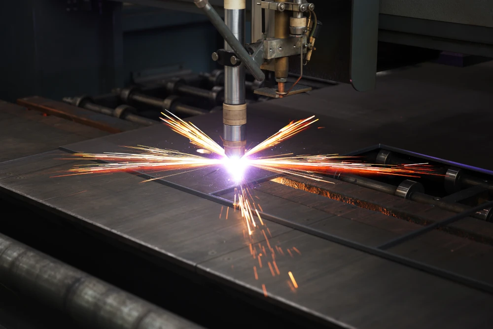
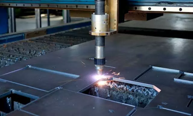
Plasma cutting is a thermal cutting process that uses a high-temperature plasma arc to melt and remove metal material along a programmed cutting path. It is commonly used for cutting electrically conductive metals, especially when working with thicker materials where speed and cutting capacity are important considerations.
This process is suitable for thick carbon steel, large components, and heavy-duty fabrication applications. Compared with laser cutting, plasma cutting is typically preferred for thicker plates and larger parts where extremely tight tolerances are not the primary requirement. It is widely used in structural fabrication, industrial equipment, machinery components, and large welded assemblies.
Plasma cutting can process various conductive metals, including carbon steel, stainless steel, and aluminum. The process provides efficient material removal for heavy plate fabrication while maintaining practical production efficiency for large-scale components.
Common applications include:
- Thick Carbon Steel – Cutting heavy steel plates used in structural and industrial applications
- Large Components – Fabricating oversized parts and assemblies that require high cutting capacity
- Heavy Plate Fabrication – Processing thicker metal sections for frames, bases, brackets, and equipment structures
- Structural Components – Cutting profiles for beams, supports, and welded structures
- Rapid Material Removal – Suitable for applications where cutting speed is prioritized over ultra-high precision
Waterjet Cutting
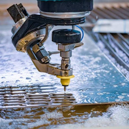
Waterjet cutting is a cold cutting process that uses a high-pressure water stream, often mixed with abrasive particles, to cut materials without generating a heat-affected zone. The process removes the risk of thermal distortion, material hardening, or heat-related surface changes, making it suitable for materials that are sensitive to heat.
This method is commonly used for stainless steel, aluminum, copper, and composite materials, as well as applications requiring clean edges and precise cutting without affecting the material properties. Waterjet cutting can handle a wide range of material thicknesses and is suitable for producing complex profiles, intricate shapes, and components with strict material requirements.
Common applications include:
- Stainless Steel – Cutting corrosion-resistant components while maintaining material properties
- Aluminum – Processing lightweight materials without heat distortion or warping
- Copper – Cutting conductive metals where thermal effects need to be minimized
- Composite Materials – Cutting layered or heat-sensitive materials without delamination
- Heat-Sensitive Applications – Suitable for parts where a heat-affected zone must be avoided
- Complex Profiles – Producing detailed contours and custom shapes with minimal edge impact
CNC Turret Punching
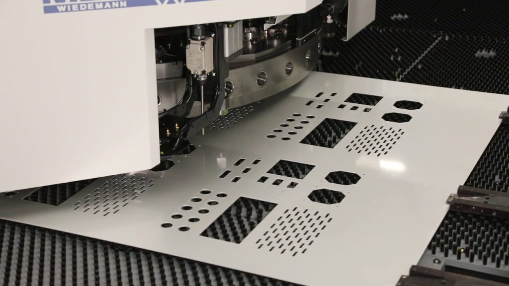
CNC turret punching is a sheet metal fabrication process that uses a computer-controlled machine equipped with multiple punching tools to create precise holes, cutouts, and formed features in metal sheets. The process uses programmed tool paths and automated tool changes to efficiently produce repetitive features with consistent accuracy.
This method is commonly used for sheet metal components requiring round holes, square holes, louvers, countersinks, and other formed features. Compared with laser cutting, turret punching is particularly suitable for parts with repeated hole patterns, standard shapes, and integrated forming operations.
CNC turret punching can also perform secondary operations such as embossing, dimpling, and marking, reducing the need for additional processing steps. It is widely used for electrical enclosures, panels, brackets, cabinets, and other sheet metal assemblies.
Common applications include:
- Round Holes – Creating ventilation holes, mounting holes, and fastener openings
- Square Holes – Producing square cutouts for specific component installation requirements
- Louvers – Forming ventilation openings and airflow features directly into sheet metal
- Countersinks – Creating recessed holes for flush-mounted screws and fasteners
- Repeated Hole Patterns – Efficient production of panels and components with multiple identical features
- Sheet Metal Forming Features – Adding embossed areas, dimples, and other functional details during punching
Step 3.Forming & Bending
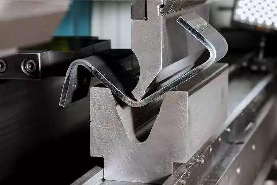
CNC Press Brake Bending
CNC press brake bending is a sheet metal forming process that uses a press brake machine to apply controlled force and create precise bends along predefined lines. The process is programmed based on CAD drawings and bending specifications, including bend angles, bend locations, material thickness, and tooling requirements.
This process is commonly used for producing 90° bends, Z bends, box formations, and fabricated brackets. CNC-controlled bending ensures consistent results across multiple parts while maintaining dimensional accuracy and repeatability. Proper bend sequencing and tooling selection are considered to prevent deformation, cracking, or interference during forming.
CNC press brake bending is widely applied in the production of enclosures, panels, frames, brackets, covers, and other sheet metal components that require accurate three-dimensional shapes.
Common applications include:
- 90° Bend – Creating standard right-angle folds for panels, brackets, and structural components
- Z Bend – Producing offset bends for mounting features, reinforcement, and assembly clearance
- Box Forming – Forming multi-sided sheet metal structures such as trays, covers, and housings
- Bracket Fabrication – Manufacturing L-brackets, mounting brackets, and support components
- Multi-Step Forming – Creating complex geometries through sequential bending operations
- Sheet Metal Enclosures – Forming panels and housings with defined dimensions and assembly requirements
Roll Bending
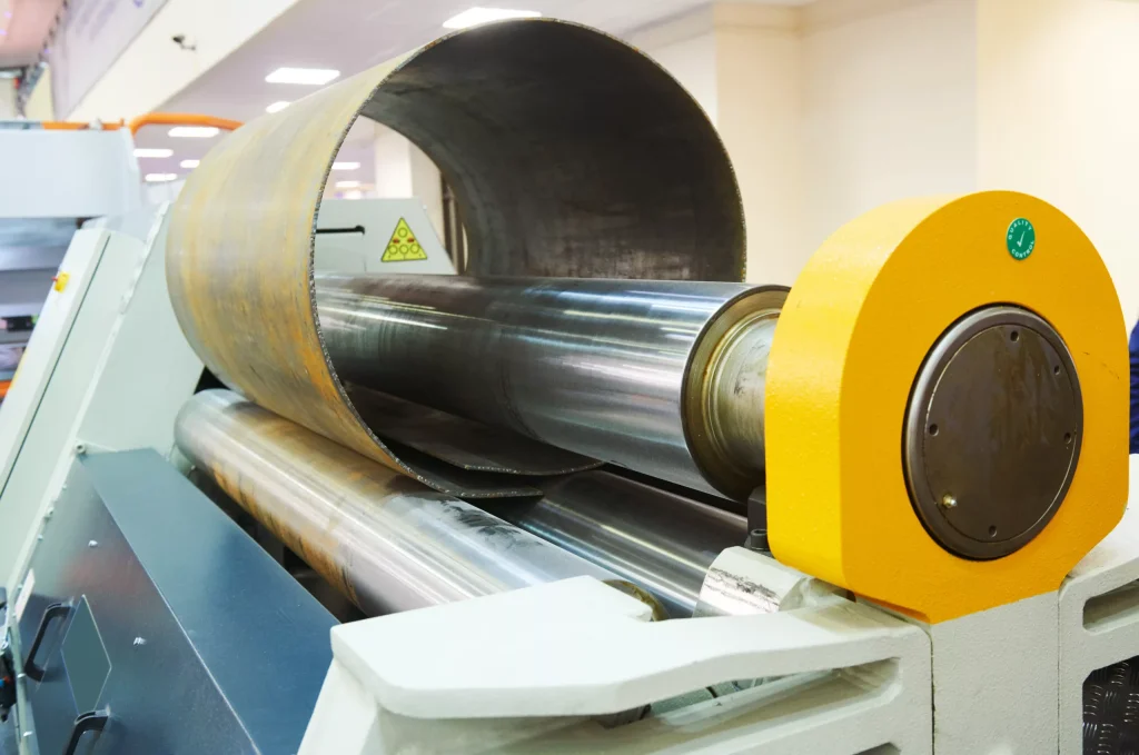
Roll bending is a metal forming process that uses a set of rollers to apply continuous pressure and gradually bend sheet metal or plate material into curved shapes. Unlike press brake bending, which creates localized bends, roll bending produces smooth, continuous curves with consistent radii.
This process is commonly used for manufacturing cylinders, curved panels, ducts, and other round or arc-shaped components. The bending radius can be controlled by adjusting roller positions and forming parameters according to material thickness, size, and design requirements.
Roll bending is suitable for a wide range of materials, including carbon steel, stainless steel, and aluminum, and is widely used in applications such as tanks, housings, pipes, ductwork, and structural components.
Common applications include:
- Cylinders – Forming cylindrical shells for tanks, vessels, and industrial components
- Curved Panels – Producing smooth curved surfaces for covers, enclosures, and architectural components
- Ducts – Fabricating curved sections for ventilation and air-handling systems
- Large Radius Bends – Creating gradual curves that cannot be achieved efficiently through standard bending methods
- Plate Rolling – Forming thick plates into circular or conical shapes for structural and industrial applications
Metal Stamping
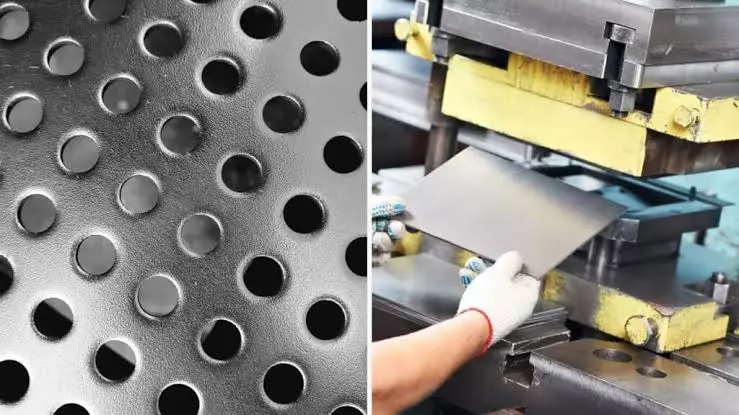
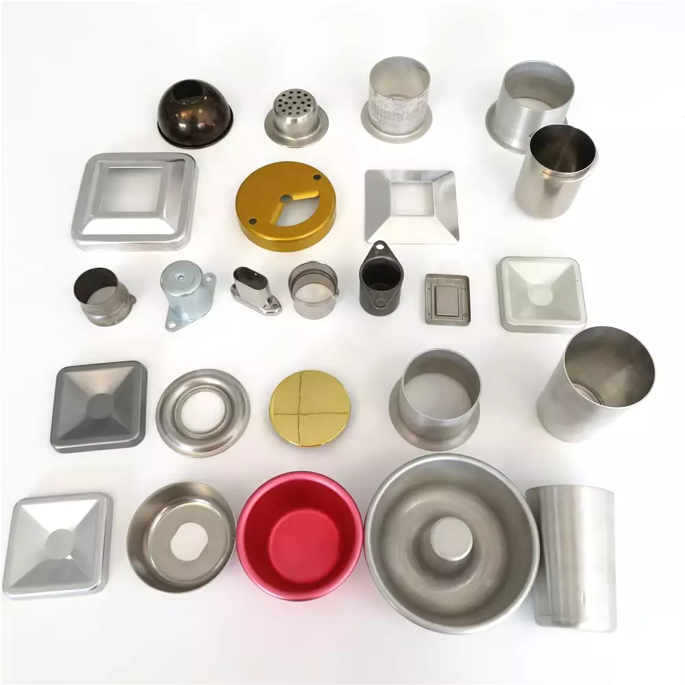
Metal stamping is a forming process that uses dies and mechanical or hydraulic presses to shape sheet metal into specific geometries. The process applies controlled force to deform the material without removing material, making it suitable for high-volume production of repeatable metal components.
This process includes various forming operations such as deep drawing, embossing, flanging, and rib forming. The selection of stamping method depends on part geometry, material properties, production volume, and functional requirements. Proper die design and process control are essential to achieve consistent dimensions and prevent defects such as cracking, wrinkling, or excessive deformation.
Metal stamping is commonly used for producing brackets, housings, panels, enclosures, automotive parts, and other sheet metal components requiring consistent shapes and efficient production.
Common applications include:
- Deep Drawing – Forming sheet metal into deep, hollow shapes such as cups, housings, and containers
- Embossing – Creating raised or recessed features for identification, reinforcement, or surface detailing
- Flanging – Forming edges or collars to improve assembly, strength, or connection points
- Rib Forming – Adding reinforcing ribs to increase structural stiffness and reduce material deformation
- High-Volume Production – Suitable for repeated production of standardized sheet metal components
Tube Bending
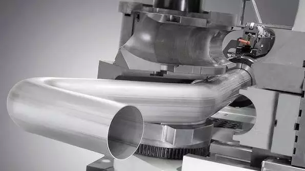
Tube bending is a metal forming process used to create curved sections in tubular materials while maintaining the required shape, dimensions, and structural integrity. The process uses specialized bending equipment to apply controlled force and form tubes according to specified bend angles, radii, and geometries.
This process is commonly applied to round tubes and square tubes used in structural frames, supports, piping systems, and fabricated assemblies. Proper tooling and bending parameters are selected based on tube material, wall thickness, bend radius, and application requirements to minimize deformation such as flattening, wrinkling, or cracking.
Tube bending is widely used for producing frames, handles, brackets, railings, exhaust systems, and custom tubular structures where continuous curved profiles are required.
Common applications include:
- Round Tube – Bending circular tubing for frames, piping assemblies, handles, and support structures
- Square Tube – Forming square tubing for structural frames, brackets, and welded assemblies
- Structural Frames – Creating curved or angled tube structures while maintaining load-bearing capability
- Custom Tube Assemblies – Producing application-specific geometries for industrial and commercial components
- Multi-Axis Bending – Creating complex tube shapes through controlled bending operations
Hydroforming
Hydroforming is a metal forming process that uses high-pressure fluid to shape metal materials into complex geometries. Instead of relying on traditional mechanical forming tools alone, the process applies hydraulic pressure to form the material against a die, allowing smooth and controlled deformation.
This process is suitable for manufacturing complex curved components and parts with integrated shapes that may be difficult to produce through conventional forming methods. Hydroforming can help reduce the need for multiple forming operations while maintaining uniform material thickness and improved structural characteristics.
Hydroforming is commonly used for automotive components, tubular structures, enclosures, and other applications requiring lightweight designs, complex contours, and precise forming control.
Common applications include:
- Complex Curved Components – Producing parts with smooth, three-dimensional geometries and irregular surfaces
- Tubular Components – Forming hollow structures such as pipes, frames, and fluid-carrying components
- Lightweight Structures – Creating strong components with optimized material distribution
- Integrated Shapes – Combining multiple features into a single formed part to reduce assembly requirements
Step 4.CNC Machining
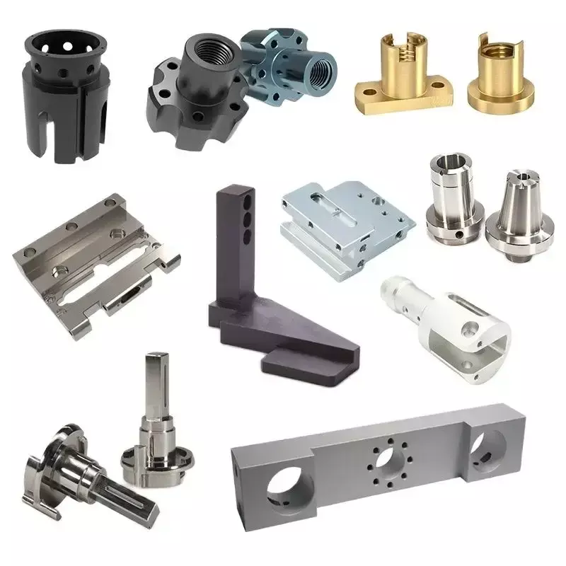
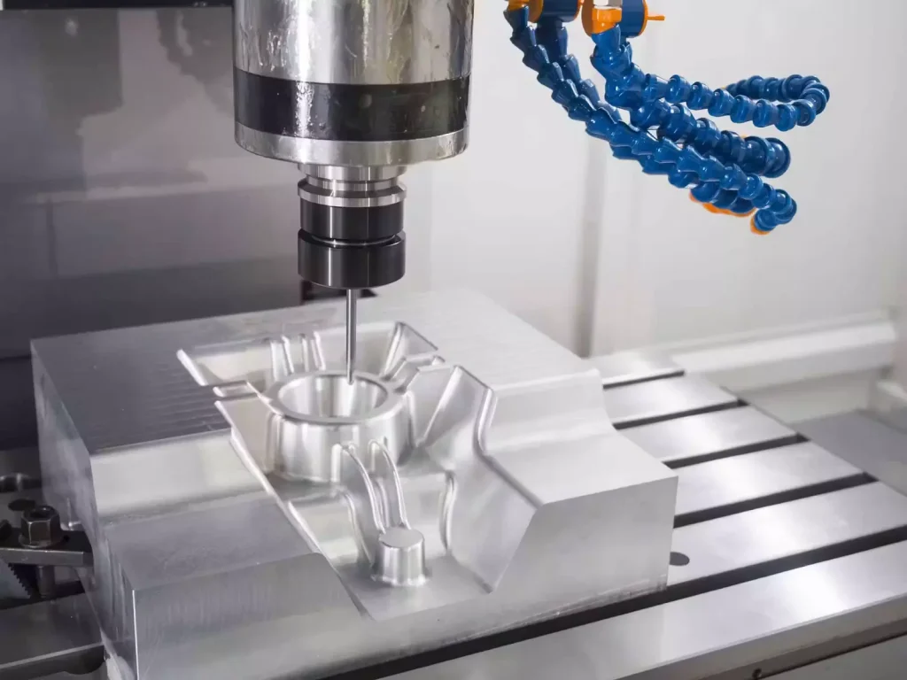
After sheet metal fabrication processes such as cutting, forming, and welding, CNC machining is often required to achieve tighter dimensional accuracy, precise features, and functional requirements that cannot be achieved through standard fabrication methods alone. Machining processes remove controlled amounts of material to refine part geometry, create precision interfaces, and complete features such as holes, threads, slots, and critical surfaces. CNC machining is commonly used for secondary operations on fabricated components, welded assemblies, and structural parts where accurate fit, alignment, and performance are required. Depending on the part design and application, different machining methods are selected, including milling, turning, drilling, tapping, and grinding.
CNC Milling
CNC milling is a machining process that uses rotating cutting tools to remove material from a workpiece according to programmed tool paths. It is commonly used for creating complex geometries, flat surfaces, pockets, slots, and precision features on metal components.
CNC milling is suitable for fabricated parts that require additional machining after forming or welding, as well as components requiring multi-axis machining and accurate dimensional control.
Common applications include:
- Machined Surfaces – Creating flat, smooth, and accurate reference surfaces
- Slots & Pockets – Producing functional cutouts and recessed features
- Complex Profiles – Machining irregular geometries and precision contours
- Assembly Interfaces – Creating accurate mounting and connection features
CNC Turning
CNC turning is a machining process where the workpiece rotates while a cutting tool removes material to create cylindrical features. It is primarily used for round components and parts requiring precise diameters, grooves, threads, or stepped profiles.
Common applications include:
- Cylindrical Components – Manufacturing shafts, pins, bushings, and fittings
- External Diameters – Achieving accurate round dimensions and surface finishes
- Threads & Grooves – Producing functional connection features
- Rotational Parts – Machining components with symmetrical geometries
Drilling & Tapping
Drilling and tapping are machining operations used to create accurate holes and threaded connections in metal components. These operations are commonly performed after fabrication to ensure proper alignment and compatibility with fasteners or assembled components.
Common applications include:
- Precision Holes – Creating mounting and alignment holes
- Threaded Holes – Producing internal threads for screws, bolts, and fasteners
- Hole Patterns – Maintaining accurate spacing and positioning requirements
- Assembly Preparation – Preparing components for mechanical fastening
Precision Grinding
Precision grinding is a finishing machining process that uses abrasive wheels to achieve highly accurate dimensions and improved surface quality. It is typically applied to components requiring tight tolerances, flatness, parallelism, or fine surface finishes.
Common applications include:
- Critical Surfaces – Refining functional contact areas and mating surfaces
- Tight Tolerances – Achieving dimensions beyond standard machining capabilities
- Surface Finishing – Improving smoothness and reducing surface irregularities
- Precision Components – Supporting applications requiring high dimensional control
Typical Tolerance Requirements
Machining tolerances vary depending on part function, material, machining method, and application requirements. Typical CNC machining tolerance ranges may include:
- General CNC Machining: ±0.05 mm to ±0.10 mm
- Precision Machining: ±0.01 mm to ±0.05 mm
- Critical Features: Tighter tolerances may be specified based on design requirements
- Surface Finish Requirements: Defined according to functional contact areas and application needs
Tolerance requirements are typically specified on engineering drawings and verified through inspection procedures before final assembly or delivery.
Step 5.Welding & Assembly
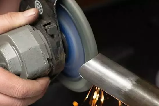
Welding and assembly join individual fabricated components into complete structures or products. The welding method is selected based on material type, thickness, joint requirements, and application needs. After welding, finishing processes are performed to improve weld appearance and surface condition, followed by trial assembly to verify fit, alignment, and overall functionality.
MIG/MAG Welding
MIG/MAG welding uses a continuously fed wire electrode and shielding gas to create strong, efficient weld joints. It is commonly used for carbon steel, stainless steel, and structural metal fabrication.
TIG Welding
TIG welding provides precise control and clean welds, making it suitable for stainless steel, aluminum, thin materials, and applications requiring high weld appearance quality.
Spot Welding
Spot welding joins overlapping sheet metal components using electrical resistance and pressure. It is commonly used for sheet metal assemblies and high-volume production.
Laser Welding
Laser welding uses a focused laser beam to create precise weld joints with minimal heat distortion. It is suitable for thin sheet metal and applications requiring controlled weld quality.
Brazing & Soldering
Brazing and soldering join metal components using filler materials without melting the base metals. These methods are used for specialized joining applications and heat-sensitive components.
Weld Seam Finishing
Weld seam finishing improves weld appearance and surface condition through processes such as grinding, polishing, and weld blending.
Trial Assembly
Trial assembly verifies component fit, alignment, and assembly requirements before final production or delivery.
Step 6.Surface Preparation
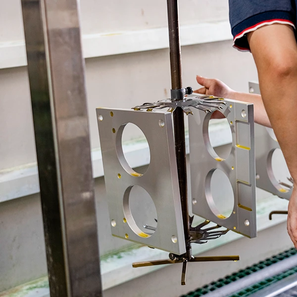
Surface preparation is an essential step before coating, painting, plating, or other finishing processes. It removes contaminants, oxidation, weld residues, and surface imperfections from fabricated components to improve coating adhesion, surface quality, and long-term performance.
The preparation method depends on the material type, surface condition, and required finish. Common processes include cleaning, mechanical treatment, and chemical treatment to create a suitable surface condition for subsequent finishing operations.
Degreasing
Degreasing removes oils, grease, coolant residues, and other contaminants left from machining, handling, or fabrication processes. A clean surface is required to ensure proper adhesion and consistency of coatings or finishes.
Grinding & Sanding
Grinding and sanding are mechanical finishing processes used to remove weld spatter, sharp edges, surface defects, and irregularities. These processes help create a smoother surface and prepare components for painting, polishing, or coating.
Sandblasting
Sandblasting uses abrasive media propelled at high speed to clean and texture metal surfaces. It removes rust, scale, oxidation, and old coatings while creating a suitable surface profile for improved coating adhesion.
Pickling
Pickling is a chemical surface treatment process that removes oxide layers, scale, and welding discoloration from metal surfaces. It is commonly used for stainless steel components to restore surface cleanliness and corrosion resistance.
Phosphating
Phosphating is a chemical conversion treatment that forms a protective phosphate layer on metal surfaces. It improves corrosion resistance and provides better adhesion for subsequent coatings such as paint or powder coating.
Step 7.Surface Finishing Options
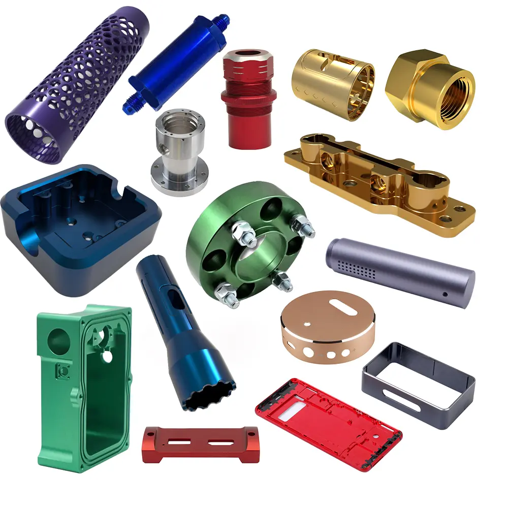
Surface finishing and coating processes improve the appearance, corrosion resistance, wear resistance, and functional performance of fabricated metal components. The selected finishing method depends on the material type, application environment, required durability, and surface appearance requirements.
These processes are typically applied after fabrication and surface preparation to provide protection against oxidation, enhance surface properties, and achieve the desired final appearance.
Powder Coating
Powder coating is a dry finishing process that applies powder material to a metal surface through electrostatic spraying, followed by heat curing to create a protective coating layer. It provides good resistance to corrosion, impact, and wear, and is widely used for fabricated parts such as enclosures, frames, brackets, and industrial components.
Liquid Painting
Liquid painting applies liquid coatings to metal surfaces through spraying or other application methods. It is suitable for large fabricated structures and components requiring specific colors, protective coatings, or customized surface finishes. Different paint systems can be selected based on indoor, outdoor, and environmental requirements.
Electroplating
Electroplating is an electrochemical process that deposits a thin metal coating onto the surface of a component to improve corrosion resistance, wear resistance, conductivity, or appearance. Common electroplating options include zinc plating, chrome plating, nickel plating, and tin plating.
Zinc plating is commonly used for steel components requiring corrosion protection. Chrome plating provides improved hardness and surface appearance. Nickel plating enhances corrosion resistance and creates a smooth finish, while tin plating is often used for electrical components due to its solderability and conductivity.
Anodizing
Anodizing is a surface treatment primarily used for aluminum components. Through an electrochemical process, a protective oxide layer is formed on the aluminum surface, improving corrosion resistance, surface hardness, and appearance while maintaining the material’s lightweight properties.
Passivation
Passivation is a chemical treatment commonly applied to stainless steel components to remove surface contaminants and restore the material’s natural corrosion resistance. It is often used after machining, welding, or fabrication processes where surface conditions may affect corrosion performance.
Polishing & Brushing
Polishing and brushing are mechanical finishing processes used to improve surface appearance and texture. Polishing creates a smoother or reflective surface, while brushing produces a uniform directional finish commonly used for stainless steel panels, enclosures, and decorative components.
Hot-Dip Galvanizing
Hot-dip galvanizing is a corrosion protection process in which steel components are immersed in molten zinc to form a durable protective coating. It is commonly used for structural steel, outdoor equipment, and applications requiring long-term resistance to environmental exposure.
Step 8.Secondary Assembly
Secondary assembly involves the installation of additional components and finishing elements after fabrication and surface treatment are completed. These operations improve the functionality, usability, and protection of fabricated parts before final inspection and delivery. Common secondary assembly processes include installing thread inserts to provide durable threaded connection points in sheet metal components, riveting for mechanical fastening without heat distortion, hardware installation for components such as screws, hinges, brackets, and fasteners, and silicone sealing or gasket installation to improve protection against moisture, dust, and environmental exposure. These processes are commonly used for enclosures, cabinets, frames, and custom metal assemblies that require additional functional components beyond the primary fabrication process.
Step 9.Quality Inspection & Packaging
Dimensional Inspection
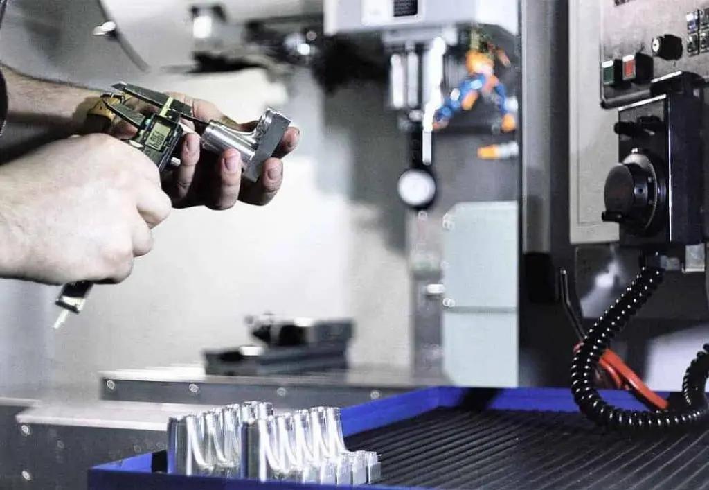
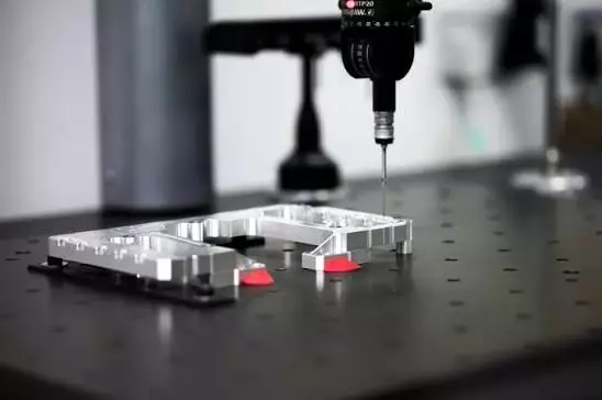
Dimensional inspection verifies that fabricated components meet the specified measurements, tolerances, and geometric requirements defined in engineering drawings. This process is performed throughout manufacturing and after final assembly to ensure part accuracy, proper fit, and consistency.
Common inspection tools include calipers for measuring basic dimensions such as length, width, and diameter, height gauges for accurate height and position measurements, and Coordinate Measuring Machines (CMM) for detailed dimensional verification of complex parts and critical features. These inspection methods help confirm that components comply with design specifications before proceeding to final delivery.
FAQ
Popular Questions
What is the metal fabrication process?
The metal fabrication process is a series of manufacturing operations used to transform raw metal materials into finished components or assemblies. It typically includes engineering design, material preparation, cutting, forming, CNC machining, welding, surface treatment, assembly, inspection, and packaging. The specific process sequence depends on the material, part design, and application requirements.
What materials are commonly used in metal fabrication?
Common materials used in metal fabrication include carbon steel, stainless steel, aluminum, brass, copper, and various structural materials such as square tubes, round tubes, angle steel, and channel steel. Material selection depends on factors such as strength, corrosion resistance, weight, fabrication method, and operating environment.
What is the difference between laser cutting and plasma cutting?
Laser cutting and plasma cutting are both thermal cutting methods, but they are used for different applications. Laser cutting is typically used for sheet metal parts requiring high accuracy, complex profiles, and smaller features. Plasma cutting is more suitable for thicker metal plates and larger components where cutting capacity and efficiency are the primary considerations.
When is CNC machining required after sheet metal fabrication?
CNC machining is required when fabricated parts need tighter tolerances, precision holes, threaded features, machined surfaces, or complex geometries that cannot be achieved through standard cutting and forming processes. It is commonly used for improving dimensional accuracy and ensuring proper fit during assembly.
What surface finishing options are available for fabricated metal parts?
Common surface finishing options include powder coating, liquid painting, electroplating, anodizing, passivation, polishing, brushing, and hot-dip galvanizing. The appropriate finish depends on the material type, corrosion protection requirements, appearance expectations, and application environment.
How is welding quality inspected?
Welding quality is inspected through visual examination, dimensional checks, and, when required, additional testing methods. Common inspection methods include checking weld appearance, weld size, joint alignment, and surface defects. For critical applications, non-destructive testing methods such as dye penetrant testing, ultrasonic testing, or radiographic inspection may also be used.
What industries use custom metal fabrication?
Custom metal fabrication is used across many industries, including industrial equipment, automotive, aerospace, construction, electronics, energy, medical equipment, food processing, and architectural applications. It is commonly used for manufacturing frames, enclosures, brackets, housings, structural components, and custom assemblies.