
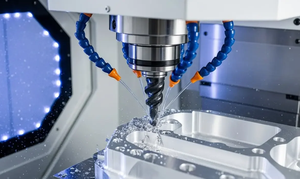
In the world of precision manufacturing, the term “tolerance” is often misunderstood as a simple measure of quality. However, walk onto any shop floor and talk to a machinist with twenty years of experience, and they will tell you a different story. To a seasoned pro, a tolerance is not just a number on a blueprint; it is a contract between design and reality that dictates cost, lead time, and the physical feasibility of the part.
This guide provides a deep dive into what constitutes “reasonable” tolerances for CNC machining, moving beyond textbook definitions to offer the practical problem-solving perspective of a master machinist.
The Reality of Precision: Why “Tightest” Isn’t Always Best
When a design arrives at a machine shop with +/- 0.005 mm (0.0002″) callouts on every single dimension, it sends a specific signal to the production team. It suggests that the part is destined for a high-stakes environment—perhaps an aerospace fuel system or a surgical robot. But if that part is merely a mounting bracket or a simple enclosure, those tight tolerances represent a significant waste of resources.
In CNC machining, precision is a hard-earned commodity. Achieving a “reasonable” tolerance means finding the “sweet spot” where the part functions perfectly in its assembly without incurring the exponential cost increases associated with over-engineering.
The Standard Baseline: ISO 2768
For most industrial applications, if a drawing does not specify a tolerance, the shop defaults to international standards like ISO 2768.
- Medium (m): This is the “safe zone” for CNC machining. It typically allows for +/- 0.1 mm for linear dimensions.
- Fine (f): Used for precision components, often requiring more frequent tool offsets and slower feed rates.
1. Typical Tolerance Ranges in Modern CNC Machining
To understand what is reasonable, we must look at the standard capabilities of modern 3-axis and 5-axis CNC machines. While a high-end machine can technically hit incredible numbers, the “reasonable” range for repeatable, cost-effective production is as follows:
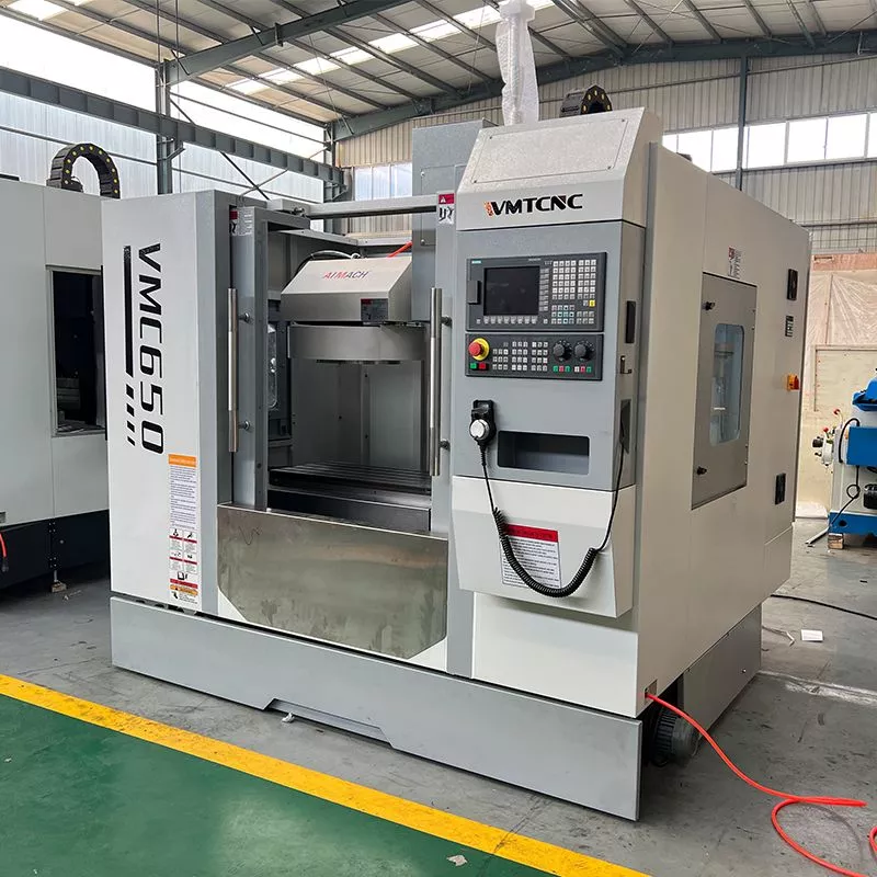
Standard Machining (+/- 0.125 mm / 0.005″)
This is the “bread and butter” of CNC work. Most vertical machining centers (VMCs) can hold this all day without breaking a sweat. It is suitable for most commercial products, brackets, and non-mating surfaces.
Precision Machining (+/- 0.025 mm / 0.001″)
This is where true engineering begins. These tolerances are required for press fits, bearing seats, and high-speed rotating components. Achieving this consistently requires sharp tooling, stable workholding, and a controlled thermal environment.
High-Precision Machining (+/- 0.005 mm / 0.0002″)
At this level, you are pushing the limits of the machine and the material. These tolerances often require specialized equipment, such as high-end Swiss lathes or jig borers, and must be inspected using a CMM (Coordinate Measuring Machine) in a climate-controlled room.
2. Factors That Influence Tolerance Achievement
A machinist doesn’t just program a number and walk away. Several physical variables determine whether a tolerance is “reasonable” or a “nightmare.”
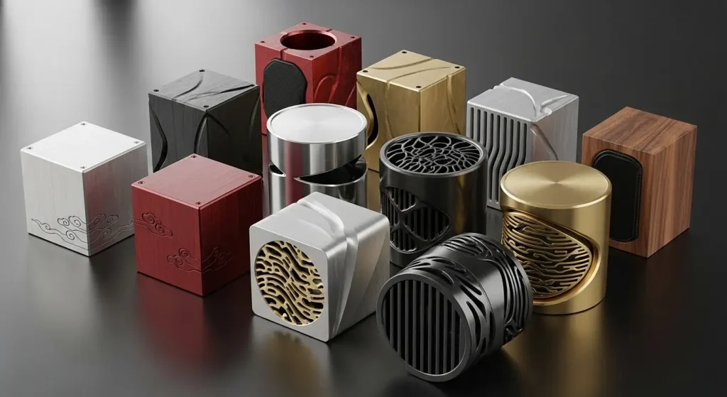
Material Selection and Stability
Not all materials are created equal.
- Aluminum 6061: Highly machinable and dimensionally stable. Holding +/- 0.02 mm is standard.
- Stainless Steel 304: Tougher on tools and prone to work hardening. The heat generated during cutting can cause the part to expand, making tight tolerances harder to verify.
- Plastics (POM, PEEK): These materials have high thermal expansion coefficients. A part measured at the machine might be out of spec by the time it reaches a cold shipping container.
Part Geometry and Wall Thickness
A “reasonable” tolerance on a solid block of steel becomes “unreasonable” on a thin-walled aluminum housing. When walls become too thin (under 1 mm), the cutting forces cause the material to deflect or “push away” from the tool. This vibration (chatter) makes it nearly impossible to hold high-precision diameters.
Tool Deflection and Wear
Every cutting tool is a cantilever. When it hits the material, it flexes. Long, thin tools (high aspect ratio) deflect more than short, stubby ones. A machinist must account for this “spring pass” to reach the final dimension, which adds time and cost.
3. The Exponential Cost-Tolerance Curve
The relationship between tolerance and cost is not linear; it is exponential. As you move from a standard tolerance to a high-precision one, the cost does not just double—it can quadruple.
Impact of Tolerance on Production Complexity
| Tolerance Range | Difficulty Level | Requirement Changes | Cost Impact |
| +/- 0.2 mm | Standard | Standard CNC setup; no special inspection. | 1.0x (Baseline) |
| +/- 0.05 mm | Precision | High-quality tooling; mid-process inspection. | 1.5x – 2.0x |
| +/- 0.01 mm | High Precision | Climate control; CMM inspection; specialized jigs. | 3.0x – 5.0x |
| +/- 0.002 mm | Ultra Precision | Sub-micron machines; diamond tooling; cleanroom. | 10x+ |
4. Master Machinist’s Advice: Designing for Success
From the perspective of the person standing at the spindle, here is how you should approach your next project to ensure it is both high-quality and cost-effective.
Use 2D Drawings for Critical Features
While 3D models are essential for programming, a 2D PDF drawing is the “legal document” of manufacturing. It is where you tell the machinist exactly where the precision matters.
- Pro Tip: Do not apply a global tolerance to the whole part. Instead, use a title block tolerance of +/- 0.1 mm for everything, and only call out +/- 0.01 mm on the specific holes or faces that actually need it.
Understand the “Hole-Shaft” Relationship
If you are designing parts that fit together, use standard fit classifications (e.g., H7/g6). This allows the machinist to use standard reamers and gauges, which are much more reliable than trying to interpolate a precise hole with an end mill.
Account for Surface Finishing
Will the part be anodized? Anodizing can add 5 to 25 microns of thickness to a surface. If you ask for a tight tolerance on a “pre-plate” dimension without accounting for the coating, the parts will not fit after finishing. A reasonable design specifies whether the tolerance applies before or after surface treatment.
5. Achievable Tolerances by Material Type
To help you select the right material for your precision needs, refer to the table below based on typical shop performance.
Material Machinability and Achievable Precision
| Material | Machinability Rating | Recommended Standard Tolerance | High-Precision Limit (Reasonable) |
| Aluminum (6061/7075) | Excellent | +/- 0.05 mm | +/- 0.008 mm |
| Brass / Copper | Very Good | +/- 0.05 mm | +/- 0.010 mm |
| Mild Steel (1018/A36) | Good | +/- 0.10 mm | +/- 0.015 mm |
| Stainless Steel (304/316) | Fair | +/- 0.12 mm | +/- 0.020 mm |
| Titanium (Gr 5) | Poor | +/- 0.15 mm | +/- 0.025 mm |
| Plastics (Delrin/PEEK) | Good (but unstable) | +/- 0.15 mm | +/- 0.050 mm |
6. How to Communicate with Your Supplier
The most successful projects are the result of a dialogue between the designer and the machinist. When requesting a quote, don’t just send files. Provide context:
- Assembly Context: Mention if the part needs to slide, press-fit, or simply bolt onto another surface.
- Inspection Requirements: If you require a full FAIR (First Article Inspection Report), specify it upfront. This requires the machinist to document every dimension, which takes time.
- Functional Surfaces: Identify which surfaces are “cosmetic” and which are “functional.” A scratch on a mounting bracket is often acceptable; a scratch on a bearing seat is not.
Conclusion: Finding the “Sweet Spot”
In CNC machining, “reasonable” is defined by functionality. A master machinist’s goal is to deliver a part that works perfectly the first time. By understanding the physical constraints of materials, the capabilities of the machines, and the exponential nature of costs, you can design parts that are both high-performing and economical.
Before you finalize your next blueprint, ask yourself: “Does this dimension truly need to be this tight, or am I just afraid of a little play?” Often, loosening a tolerance by just 0.05 mm can save you thousands of dollars in the long run without sacrificing an ounce of performance.
Ready to optimize your design for manufacturing? Submit your 2D drawings and 3D models for a comprehensive DFM (Design for Manufacturability) review. Our engineering team can help you identify where to tighten up and where to let go, ensuring your project stays on budget and on schedule.


