
5-Axis CNC Machining Case Studies Across Automotive, Robotics & Energy Industries
Our Service
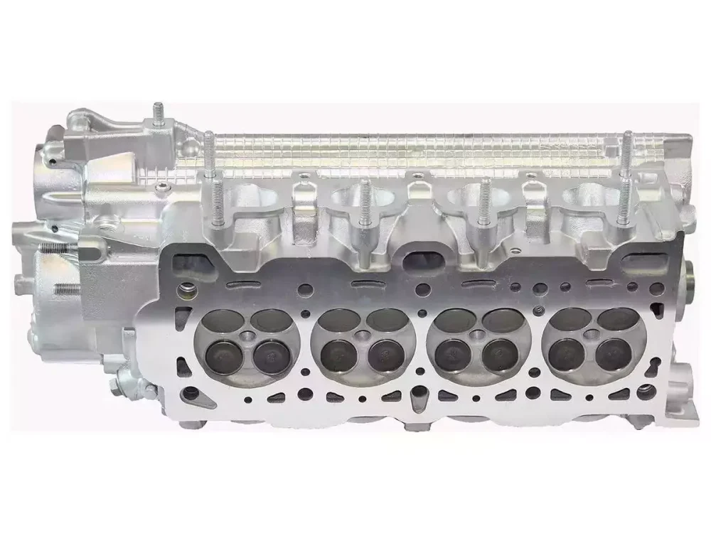
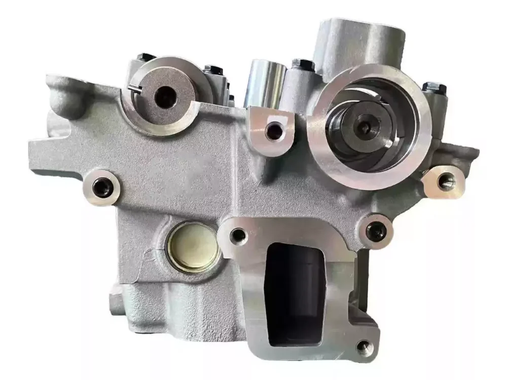
Precision 5-Axis CNC Machining of Automotive Engine Cylinder Head
🔷Engineering Pre-Processing Layer
Drawing Review & DFM Engineering Analysis
Customer 3D models and 2D GD&T drawings are reviewed to evaluate tolerance feasibility, datum relationships, and manufacturability.
Multi-surface combustion chamber and internal cooling structures are analyzed to confirm 5-axis simultaneous machining requirements and eliminate re-clamping errors and tolerance stack-up risks.
Machine & Fixture Configuration
High-precision 5-axis machining center with modular fixture system is used.
Single-setup machining strategy ensures all sealing surfaces, inclined holes, and combustion chamber geometries are completed without datum shift.
- 5-Axis Simultaneous Machining
- Single-Setup Error Elimination
- Collision-Free CAM Simulation
- Thin-Wall Deformation Control
- Traceable CMM & GD&T Inspection
- DFM-Optimized Batch Production
Our Service
Manufacturing Execution Layer CAM & Toolpath Strategy
🔷5-axis simultaneous machining for combustion chamber surfaces
Adaptive roughing for stable chip load control
Optimized tool engagement to reduce vibration in thin-wall areas
Tooling Strategy
Carbide end mills for aluminum roughing
Ball-end tools for chamber finishing
Long-reach anti-vibration tools for deep coolant channels
Deformation Control Strategy
Layered material removal to release internal stress gradually
Symmetrical machining sequence to balance thermal load
Controlled finishing feed to reduce thin-wall deflection
- 5-Axis Simultaneous Machining for Chambers
- Adaptive Roughing for Stable Chip Load
- Optimized Tool Engagement Reduces Vibration
- Application-Specific Tooling for Deep Channels
- Layered Material Removal Releases Stress
- Symmetrical Machining Balances Thermal Load
Our Service
Process Verification and Traceable Quality Control
🔷Toolpath Simulation & Collision Check
Full CAM simulation is performed before machining to verify tool collision, spindle clearance, and workpiece interference, ensuring stable long-cycle production.
🔷In-Process & Final Inspection
Probe-based datum verification during machining
Full CMM inspection of combustion chamber geometry
Valve seat concentricity and sealing accuracy verification
Surface roughness control (Ra ≤ 0.8 μm on sealing faces)
Post-Machining Treatment & Final Validation
Deburring, ultrasonic cleaning, corrosion protection, and surface finishing are applied.
Final inspection reports include full traceable dimensional records.
- CAM Simulation Prevents Workpiece Damage and Delays
- In-Process Probing Guarantees Precise Machining Datums
- CMM Verification Delivers Certified Geometric Accuracy
- Sealing Surfaces Consistently Meet Ra 0.8 um Max
- Ultrasonic Cleaning Prepares Parts for Immediate Assembly
- Traceable Reports Provide Full Dimensional Transparency
Our Service
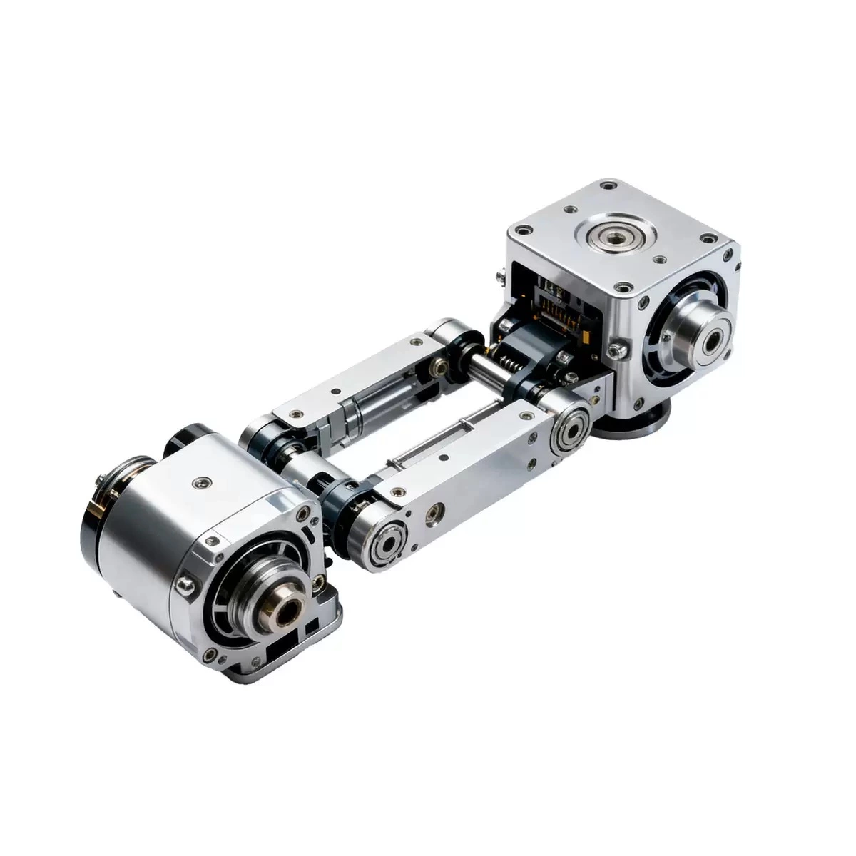
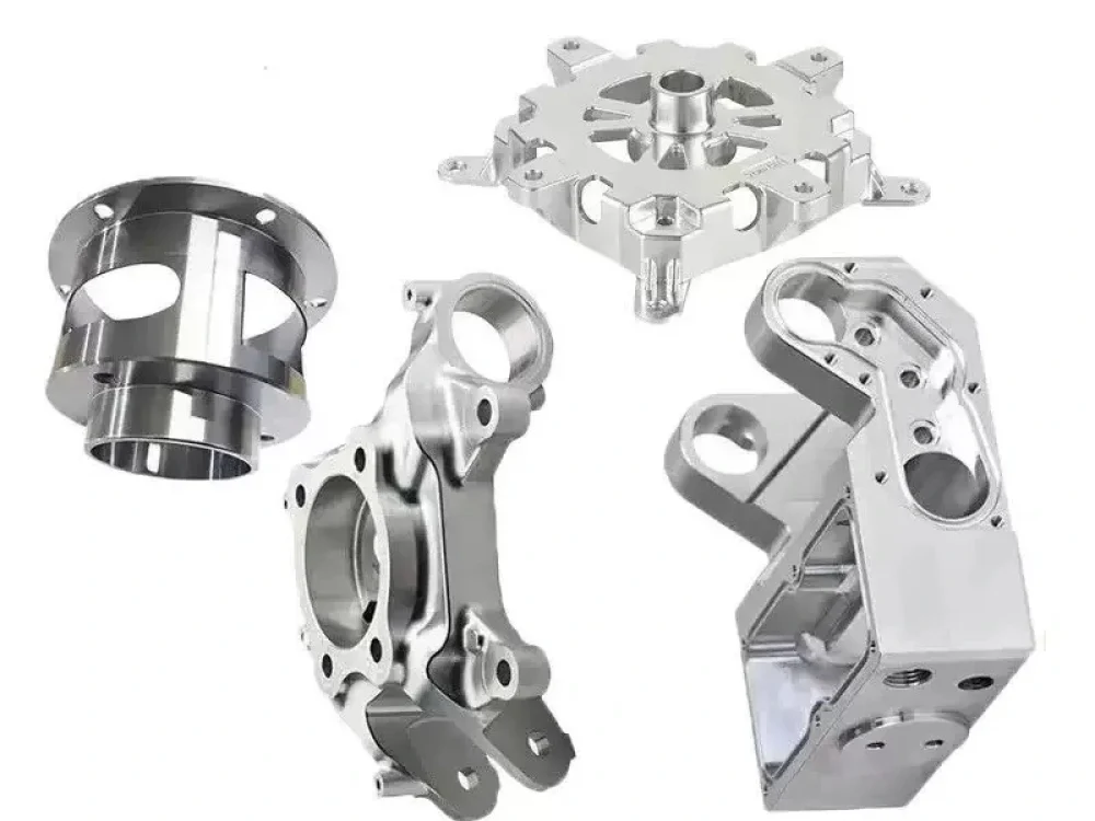
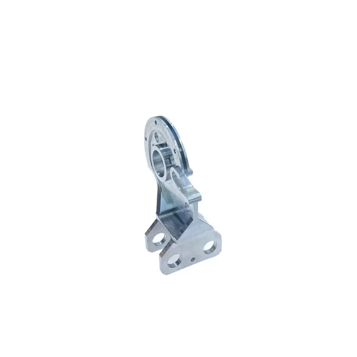
Precision CNC Machining of Industrial Robot Joint Housing
🔷Engineering Pre-Processing Layer
Drawing Review & DFM Engineering Analysis
Bearing load paths and assembly geometry are analyzed based on customer 3D models.
Critical coaxiality between bearing seats and mounting interfaces is validated to ensure motion accuracy and assembly stability.
Machine & Fixture Configuration
5-axis machining center with rigid fixture system ensures structural stability during heavy material removal and precision finishing.
- Precision Coaxiality Validation Protects Robotic Motion Accuracy
- Pocket Optimization Maintains Maximum Component Structural Rigidity
- Controlled Finishing Around Bearing Zones Eliminates Play
- Stepwise Material Removal Stabilizes Long-Term Part Geometry
- Flatness Inspection Prevents Gaps on Mounting Interfaces
- Flawless Part Validation Eliminates Robotic Assembly Issues
Our Service
Manufacturing Execution Layer CAM & Toolpath Strategy
🔷Continuous toolpath machining for bearing alignment
Pocket optimization to reduce vibration
Smooth transition paths to maintain rigidity
Tooling Strategy
Precision boring tools for bearing seats
Solid carbide cutters for structural machining
Anti-vibration tool holders for deep cavity finishing
Deformation Control
Symmetrical roughing strategy
Stepwise material removal to stabilize structure
Controlled finishing around bearing zones
- Continuous Toolpaths Ensure Smooth Bearing Seat Alignment
- Pocket Optimization Protects Parts from Tool Vibration
- Smooth Transition Paths Maintain High Structural Rigidity
- Precision Boring Tools Achieve Strict Bearing Tolerances
- Anti-Vibration Tool Holders Perfect Deep Cavity Finishing
- Symmetrical Roughing Strategy Balances Internal Material Stress
Our Service
Simulation-Driven Verification and Rigorous Quality Inspection
🔷 Digital Verification Layer
Toolpath Simulation & Collision Check
Full simulation ensures safe machining of deep cavities and avoids tool interference in complex rib structures.
🔷 Quality Control & Post-Processing Layer
Inspection System
CMM bearing axis alignment measurement
Roundness and coaxiality verification
Flatness inspection of mounting surfaces
In-process probing compensation
Post-Machining Treatment
Deburring, cleaning, anti-corrosion treatment, and final dimensional documentation.
- Digital Twin Verification Lowers Project Executive Risks
- Proactive Interference Screening Protects Thin Rib Integrity
- Metrology-Grade Diagnostics Certify Structural Precision
- Geometrical Form Control Maximizes Joint Motion Efficiency
- Interface Micro-Flats Optimization Secures Rigid Assemblies
- Post-Process Conditioning Extends Component Operational Lifespan
Our Service
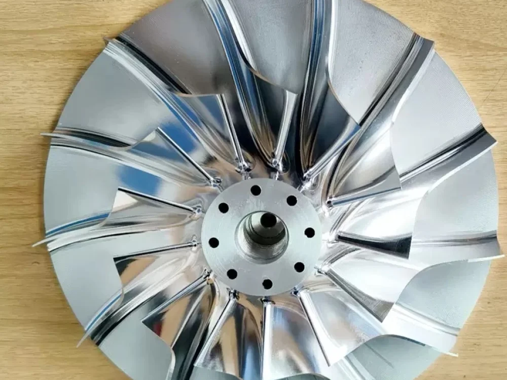
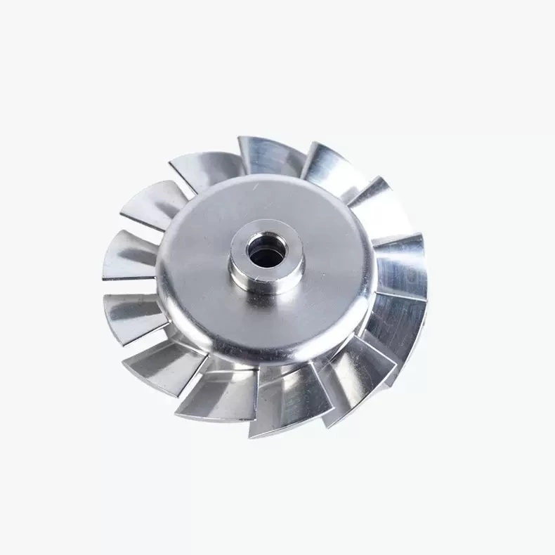
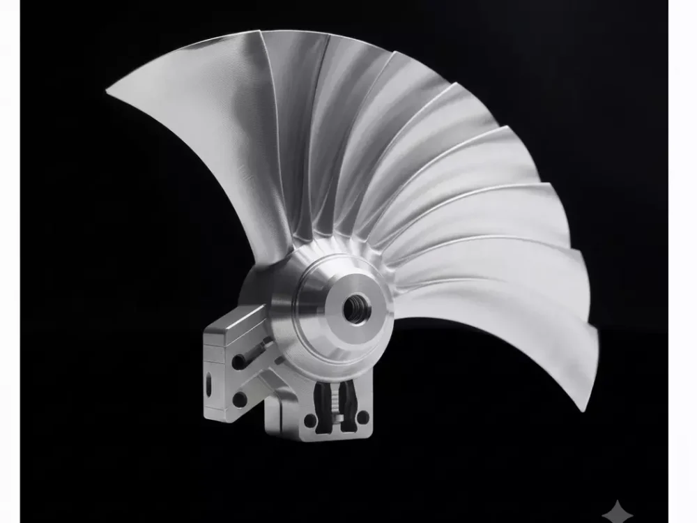
5-Axis CNC Machining of Gas Turbine Structural Component
🔷 Engineering Pre-Processing Layer
Drawing Review & DFM Engineering Analysis
Aerodynamic surface geometry and thermal load behavior are analyzed based on 3D engineering models.
Machining feasibility of nickel-based alloys is evaluated to ensure stable cutting performance under high thermal stress.
Machine & Fixture Configuration
High-rigidity 5-axis machining center with thermal-stable fixture system ensures geometric accuracy during long-cycle machining.
- Aerodynamic Surface Analysis Preserves Design Geometric Integrity
- Thermal Load Simulation Prevents Material Stress Deformation
- Nickel-Based Alloy Evaluation Guarantees Reliable Tool Performance
- High-Thermal Stress Strategies Mitigate Machining Risk Factors
- High-Rigidity 5-Axis Machining Secures Extreme Component Accuracy
- Thermal-Stable Fixtures Maintain Stability During Long Cycles
Our Service
Manufacturing Execution Layer CAM & Toolpath Strategy
🔷Continuous 5-axis aerodynamic surface machining
Constant scallop height finishing strategy
Adaptive toolpath control for heat reduction
Tooling Strategy
Coated carbide tools for heat-resistant alloys
Ceramic finishing tools (where applicable)
High-pressure coolant for thermal stability
Thermal & Deformation Control
Controlled material removal rate
Adaptive feed adjustment in high-load zones
Sequential machining to balance thermal expansion
- Constant Scallop Finishing Delivers Exceptional Surface Uniformity
- Adaptive Toolpath Control Effectively Lowers Cutting Heat
- Coated Carbide Tools Efficiently Machine Heat-Resistant Alloys
- High-Pressure Coolant Jet Maintains Dynamic Thermal Stability
- Regulated Material Removal Rates Eliminate Severe Cutting Stress
- Sequential Machining Effectively Balances Thermal Expansion Effects
Our Service
Digital Geometric Validation and Flow Performance Quality Assurance
🔷 C. Digital Verification Layer
Toolpath Simulation & Collision Check
Full CAM simulation ensures safe multi-axis motion and eliminates interference risk in complex aerodynamic geometries.
🔷 D. Quality Control & Post-Processing Layer
Inspection System
Full CMM inspection of aerodynamic surfaces
Surface profile verification for flow performance
Roundness and alignment testing
Thermal stability evaluation during inspection
Post-Machining Treatment
Deburring, ultrasonic cleaning, corrosion protection, and final traceable inspection documentation.
- Multi-Axis Motion Simulation Eliminates Complex Geometric Interference
- Aerodynamic Surface Metrology Validates Designed Flow Performance
- Surface Profile Verification Secures Optimal Fluid Dynamics
- Thermal Stability Evaluation Prevents Inspection Dimension Fluctuations
- Rigorous Roundness and Alignment Testing Confirms Assembly Integrity
- Traceable Inspection Documentation Streamlines Customer Compliance Audits