
If you work with CNC milling machines, you already know something: when parts go out of tolerance, it’s almost never “random.”
It’s usually the machine’s components talking to you—through chatter, poor surface finish, or missed dimensions.
In this guide, you’ll break down every major CNC milling machine component—from the machine base and column, to the spindle assembly, axis drive system, CNC controller, automatic tool changer, and more.
You’ll see how each part actually affects:
- Accuracy and repeatability
- Tool life and surface finish
- Cycle time and reliability
Whether you’re running parts daily, learning CNC, or planning upgrades, understanding these CNC milling machine components is one of the fastest ways to improve real-world results—and it’s exactly how shops like MS Machining deliver consistent, high‑precision parts.
Let’s get straight into the hardware that really matters.
Overview of CNC Milling Machine Structure
When people first look at a CNC milling machine, it can feel like a giant, expensive mystery. What does each part actually do? Which components matter most for accuracy, surface finish, and uptime? And how do CNC milling machine components affect your costs and lead times in real production?
At its core, a CNC milling machine is a rigid structure that holds:
- The workpiece (your part)
- The cutting tools
- The motion system that moves tools and parts with precision
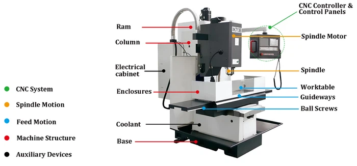
The major CNC milling machine parts include:
- Machine base and column – the main frame that provides rigidity and absorbs vibration
- Worktable and workholding – where you clamp your material using vices, fixtures, T-slots, or modular systems
- Spindle assembly – rotates the cutting tool at high speed with high precision
- X, Y, Z axis drive system – ball screws, linear guides, and servo motors that move the table or head
- CNC controller and electronics – the “brain” that reads the program and coordinates all movement and cutting
- Cooling, lubrication, and chip management – keeps tools, spindle, and guides alive and the cut stable
Understanding how these CNC precision machining components work together is the foundation for better process decisions, tighter tolerances, and longer machine life.
Vertical vs Horizontal CNC Milling Machine Components
Most US shops work mainly with vertical milling machine components, but horizontal milling machine parts are just as important when you’re chasing serious productivity.
Vertical CNC mills (VMCs):
- Spindle is vertical, pointing down toward the worktable
- Work sits on a flat table with T-slots
- Easier to set up and program, ideal for job shops, prototypes, and short runs
- Common for cnc steel, sheet metal machining, and general metal fabrication parts
Horizontal CNC mills (HMCs):
- Spindle is horizontal, pointing toward the side of the workpiece
- Use rotary tables, pallets, and tombstones for multi-side machining
- Better natural chip evacuation and more efficient for high-volume machining
- Often paired with pallet changer systems for lights-out production
Structurally, you’ll still see a base, column, spindle, axis drives, and CNC controller in both styles, but the orientation of the spindle, axis layout, and workholding strategy is what separates vertical from horizontal CNC milling machine components.
Basic Working Principle of CNC Milling Machines
Every CNC mill—whether 3-axis, 4-axis CNC milling machine, or 5-axis CNC milling machine components—follows the same basic principle:
- You define the geometry
- A CAD model of your cnc precision turned parts, metal fabrication parts, or machined components.
- CAM generates toolpaths
- CAM software converts geometry into toolpaths and a CNC program (G-code).
- The CNC controller executes
- The CNC controller unit reads the G-code and calculates motion for each axis.
- Axis drive system moves the machine
- Servo motors or stepper motors, ball screws, and linear guides move:
- X-axis (left-right)
- Y-axis (front-back)
- Z-axis (up-down)
- Servo motors or stepper motors, ball screws, and linear guides move:
- Spindle and tool cut the material
- The spindle motor and drive spin the cutting tool.
- Controlled motion + correct speeds and feeds = controlled material removal.
- Feedback maintains accuracy
- Encoders and linear scales send position data back to the controller.
- The system corrects errors to maintain accuracy and repeatability.
That’s the core: controlled movement of a rotating tool against a fixed or moving workpiece, driven by a CNC program and precision mechanical components.
Why Understanding CNC Milling Machine Components Matters
If you care about cost per part, uptime, or quality, understanding CNC milling machine components is not optional. It directly impacts:
- Accuracy and repeatability
- High-quality spindle assembly, ball screws, and linear guides mean better tolerance control and fewer rejected parts.
- Surface finish and tool life
- A rigid cnc machine base and column, good spindle bearings, and proper cnc coolant system give you cleaner surfaces and longer-lasting tools.
- Troubleshooting and downtime
- Knowing how axis drive systems, feedback devices, ATC systems, and cnc lubrication systems work helps you diagnose vibration, chatter, position errors, and tool-change issues quickly.
- Choosing the right machine and upgrades
- Whether you’re machining cnc steel, aluminum, or complex sheet metal machining jobs, your success depends on:
- Spindle power and rigidity
- Axis drive quality
- Workholding flexibility
- Chip removal and coolant capacity
- Whether you’re machining cnc steel, aluminum, or complex sheet metal machining jobs, your success depends on:
When I design and run production for cnc precision machining components, metal fabrication parts, and CNC steel parts for the US market, I treat the machine as a system: every component affects quality, speed, and reliability. The more you understand your cnc milling machine parts diagram in real-world terms, the more control you have over your process and your bottom line.
Core Structural Components of a CNC Milling Machine
When I’m looking at a CNC milling machine, the first thing I judge is the iron. The core structural components decide how accurate, rigid, and stable your cnc milling machine components really are.
Machine base and frame
The machine base and frame are the foundation of all CNC milling machine parts. A solid base gives:
- Rigidity to handle heavy cuts in cnc steel and aluminum
- Vibration damping for better surface finish and tool life
- Accuracy over long runs, especially in cnc precision machining components
On quality machines, you’ll see a heavy cast-iron or mineral cast base with wide contact surfaces and internal ribs to kill vibration.
Column and support structure
The column and support structure carry the spindle assembly in CNC milling and take all cutting forces:
- Must be massive and well-braced to keep the spindle from deflecting
- Often uses box castings with internal ribs for stiffness
- Directly impacts machining accuracy and repeatability
When I’m comparing machines for our own shop or for customers looking at advanced 5-axis CNC options, the column design is always on my short list.
Knee structure in vertical milling machines
On traditional vertical milling machine components, the knee is the big casting that moves up and down on the column:
- Supports the saddle, cross slide, and worktable
- Allows manual or powered adjustment of the Z height
- Needs tight gibs and good lubrication to avoid chatter and wear
Many modern VMCs move the table in X/Y and the spindle in Z instead of using a knee, but you’ll still see knee-style vertical mills in job shops across the U.S.
Cross slide, saddle, and dovetail ways
The cross slide and saddle link the table to the base and give you smooth X/Y motion:
- Saddle rides on the base; cross slide carries the table
- Dovetail ways or box ways provide guidance and support
- Proper scraping, alignment, and lubrication are critical for cnc machine accuracy and repeatability
Whether I’m setting up prototype work or repeat production, if the base, column, knee, saddle, and ways are right, everything else on the CNC milling machine can actually deliver the precision we’re selling.
Workholding Components and Table System
CNC milling machine worktable and T-slots
On any CNC milling machine, the worktable and T-slots decide how rigid and repeatable your setup is.
Most CNC tables are:
- Cast iron or hardened steel for stiffness and vibration damping
- Laid out with standard T-slots (typically 3–5 slots) for flexible clamping
- Precision ground so your cnc precision machining components sit flat and stay in tolerance
If you’re machining cnc steel, aluminum, or complex metal fabrication parts, a solid worktable with accurate T-slots is non‑negotiable.
Vises, clamps, and fixtures
To keep parts from moving under cutting forces, I rely on a mix of:
- CNC vises – Fast, repeatable, ideal for production runs and cnc milling machine components
- Step clamps and strap clamps – Flexible for odd‑shaped parts and short runs
- Dedicated and modular fixtures – Best for high-volume cnc precision turned parts, sheet metal machining, or repeat metal fabrication jobs
Good workholding is what lets you actually hold the tolerances your machine is capable of.
Rotary tables and indexers
When I need multi-side machining without constant re-clamping, I add:
- Rotary tables – Turn the part around one axis for 4th-axis style work
- Indexers – Lock the part into precise angular positions for features on different faces
These are key for higher-value cnc milling components, manifolds, and complex metal blocks, especially when you want to cut setups and labor.
Pallet changers and modular fixturing
For U.S. shops focused on uptime, pallet and modular systems are a game changer:
- Pallet changers let you load one pallet outside the machine while the other is cutting
- Modular fixturing plates (grid plates, zero-point systems) let you swap jobs fast with repeatable location
This is how I keep spindles cutting instead of sitting idle. If you’re running mixed work—cnc steel, alloys, or sheet metal machining—pairing strong workholding with high-precision machines and services like our CNC precision machining solutions lets you push cycle times down while holding tight tolerances.
Spindle Assembly and Head Components
When you’re chasing accuracy and surface finish, the spindle assembly is the heart of your CNC milling machine components.
CNC Spindle Unit and Cartridge Design
Most modern CNC milling machine parts use a spindle “cartridge” design:
- Pre-assembled unit with shaft, bearings, seals, and drawbar in one cartridge
- Swaps out faster for service, which keeps downtime low
- Built for high rigidity so you can push feeds and speeds without chatter
On our CNC mills and in our cnc precision machining components work, we always spec cartridge-style spindles for repeatable performance and easier maintenance.
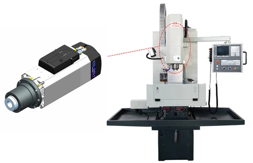
Spindle Motor, Drive Belt, and Direct Drive Systems
You’ll mainly see two drive styles on U.S. shop floors:
- Belt-driven spindles
- Good torque at lower RPM
- More forgiving on crashes (belt can slip)
- Cost-effective for general cnc steel, aluminum, and metal fabrication parts
- Direct-drive spindles
- Motor is coupled directly to the spindle
- Higher RPM, smoother running, less vibration
- Ideal for high-speed cnc milling components and tight-tolerance work
For high-mix, high-precision work like we do in our CNC milling services, direct-drive often wins on finish and tool life.
Spindle Bearings and Cooling Systems
Spindle bearings carry all the cutting load, so quality matters:
- Angular contact bearings for high speed and precision
- Preloaded bearing stacks to control runout and thermal growth
- Air-oil or grease lubrication depending on speed and duty cycle
Cooling is just as critical:
- Fan or liquid-cooled spindle housings to keep temperature stable
- Better thermal control = more consistent size and less drift on long runs
If you’re pushing long cycles on stainless or cnc steel parts, a cooled spindle pays for itself in consistency.
Spindle Nose, Taper Types, and Tool Retention
The spindle nose is where all the accuracy meets the tool:
- Common tapers: BT, CAT, HSK for most CNC milling machines in the U.S.
- BT/CAT: robust, great for general job shop work and heavy cuts
- HSK: shorter, dual-contact, ideal for high-speed, high-precision cutting
Tool retention is handled by:
- Pull studs (retention knobs) on the holder
- Drawbar mechanism (disc springs + hydraulic or pneumatic release)
A rigid taper and strong retention system directly affect:
- Surface finish
- Tool life
- Ability to rough hard materials and still hold tolerance
If you’re choosing a new machine or upgrading, spindle design (taper type, drive style, cooling) should be one of the first cnc milling machine components you compare.
Axis Drive System and Motion Control in CNC Milling Machines
The axis drive system is one of the most important CNC milling machine components if you care about accuracy, speed, and finish. When I spec or build a CNC mill, I treat the motion system (X, Y, Z + any rotary axes) as the backbone of the machine’s performance.
X, Y, Z Axis Layout and Travel
Most CNC milling machines use:
- X-axis – left/right table movement
- Y-axis – front/back table or saddle movement
- Z-axis – up/down spindle or knee movement
Key things I look at:
- Travel ranges: More travel means larger parts and fewer setups.
- Axis clearance: Enough space for vises, fixtures, and rotary tables.
- Support and rigidity: Short, well-supported axes flex less and cut cleaner.
For U.S. job shops running cnc precision machining components or short-run metal fabrication parts, I always recommend checking the axis travels first—they decide what work you can actually take on.
Ball Screws, Lead Screws, and Linear Guides
Modern CNC milling machine parts use a combination of:
- Ball screws
- Low friction, high efficiency
- Very low backlash when preloaded
- Ideal for high-accuracy cnc steel, aluminum, and sheet metal machining
- Lead screws
- More common on light-duty or older machines
- Less accurate and more wear over time
- Linear guides (linear rails)
- Roller or ball type
- High stiffness and smooth motion at high feed rates
- Critical for holding tolerances during heavy cuts
On my machines, I always go ball screws + linear guides for serious cnc milling components work. That combo is a big part of why modern CNC mills can hit tight tolerances consistently.
Servo Motors vs Stepper Motors
The axis drive system is typically powered by either:
- Servo motors (most pro CNC mills)
- Closed-loop with encoders
- High torque at speed
- Excellent positioning and repeatability
- Best for high-speed, high-precision cnc milling machine components
- Stepper motors (light-duty/desktop)
- Open-loop in many systems
- Lower cost, simpler drives
- Easier to lose steps under load
For production cnc milling, cnc precision turned parts, or complex metal fabrication and bending work, I strongly prefer servo motors. They pay for themselves in uptime, reliability, and finished part quality.
4-Axis and 5-Axis Rotary and Tilt Components
When you step up to 4-axis and 5-axis CNC milling machines, you’re adding:
- 4th axis (A or B) – rotary table that spins the part for machining multiple sides
- 5th axis – tilt or trunnion table that tilts and rotates the part for full 3D access
Common 4-axis / 5-axis cnc milling machine components include:
- Rotary tables and trunnions with high-torque servo motors
- High-precision bearings and brakes to lock position under heavy cuts
- Integrated encoders for accurate angular feedback
Shops in the U.S. moving into impellers, complex housings, or high-value aerospace parts will usually get the biggest jump in capability from a solid 4-axis or 5-axis setup, paired with a rigid axis drive system and quality motion control.
If you want to see how a full CNC system comes together beyond just the motion hardware, I break this down in more detail on our main guide to CNC milling machines and their components.
CNC control system and electronics
When you’re chasing tight tolerances and repeatable results, the CNC control system and electronics matter just as much as the iron. Here’s how I look at the key CNC milling machine components on the control side.
CNC controller (MCU) and motion control hardware
The CNC controller (MCU) is the “brain” of the machine. It reads the G-code, calculates motion paths, and synchronizes every axis and spindle move.
- Modern controllers handle look-ahead, jerk control, and high-speed machining.
- Quality motion control hardware (drive boards, I/O modules, safety relays) cuts down on chatter, positioning errors, and random alarms.
- For precision work—like micro features or tight-tolerance cnc milling machine components—controller quality directly affects finish and cycle time.
Operator control panel, HMI, and manual controls
The operator panel and HMI are where your team lives every day.
- Clear HMI screens, logical menus, and shortcut keys reduce setup time and operator mistakes.
- Handwheels, jog buttons, and feed/spindle override knobs give fast manual control for setups and proving out programs.
- Good panel design means less training time and fewer fat-finger errors on the shop floor.
Electrical cabinet, drives, and power supply units
All the power and brains are housed in the electrical cabinet.
- Servo drives, spindle drives, and regulated power supplies must be sized and cooled correctly to run 24/7.
- Clean wiring, labeled terminals, and proper grounding make troubleshooting and upgrades faster.
- Stable power and good drive tuning help maintain accuracy on demanding cnc precision machining components.
Feedback devices, encoders, and linear scales
Feedback is how the machine “knows” where it really is, not just where it thinks it is.
- Rotary encoders on servo motors are standard for most X, Y, Z axis drive systems.
- Linear scales mounted on the axes give true position feedback at the machine structure, boosting accuracy and repeatability, especially in thermal drift.
- High-resolution feedback is crucial when we’re machining high-value materials like stainless steel components with CNC machining or tight-tolerance cnc milling parts.
If you care about finish quality, uptime, and real-world positioning accuracy, you can’t treat the CNC control system and electronics as an afterthought—they’re core cnc milling machine parts that decide how much performance you actually get from the iron.
Tooling, Tool Holders, and ATC Systems
When you’re chasing real productivity from a CNC milling machine, the tooling, tool holders, and ATC system matter just as much as the iron. This is where you gain or lose cycle time, accuracy, and consistency.
Tool Holder Types: BT, CAT, HSK, ER Collets
In most CNC milling machine components, you’ll see these common tool holder standards:
- BT holders (BT30/BT40/BT50)
Balanced design, good for high-speed CNC precision machining. Very common on Asian and European machines. - CAT holders (CAT40/CAT50)
Standard in many U.S. shops. Rugged, widely supported, great for heavy cnc steel and metal fabrication parts. - HSK holders (HSK63, etc.)
Short, hollow shank. Excellent rigidity and runout control at high speed, ideal for tight-tolerance cnc milling components and aluminum machining. - ER collet chucks (ER16/ER32/ER40)
Flexible option for drills, small end mills, and cutters with straight shanks. Good grip and easy tool swaps.
I always match holder quality to the work: higher-end BT/HSK for precision surface finishes, ER collets for flexible setups.
Tool Retention, Pull Studs, and Drawbar
Tool retention in the spindle assembly is handled by:
- Pull studs (retention knobs): Thread into the back of BT/CAT holders; this is what the drawbar grabs. Poor-quality studs are a reliability risk.
- Drawbar mechanism: Spring (Belleville) stacks or hydraulic systems clamp the tool holder, and a pneumatic/hydraulic cylinder releases it for tool change.
- Gripper fingers / clamping segments: Sit inside the spindle taper and lock onto the pull stud.
If you start seeing tool pullout, taper fretting, or inconsistent tool changes, this area of the cnc spindle assembly is the first place I inspect.
Automatic Tool Changer (ATC) Types and Magazines
The ATC is what keeps a CNC milling machine cutting instead of sitting idle:
- Drum-type ATC:
Compact, fast indexing. Great for small and mid-size vertical milling machine components where space is tight. - Arm-type ATC:
Dual-arm design swings tools between spindle and magazine. Faster change times, common on higher-end 4-axis cnc milling machine and 5-axis cnc milling machine components. - Chain / carousel magazines:
Higher tool capacity (30+ tools). Ideal for complex jobs, lights-out runs, and mixed cnc milling parts.
A reliable automatic tool changer system is non‑negotiable if you’re running high-mix, low-volume work or unattended shifts.
Common Cutting Tools for CNC Milling
For most U.S. job shops and OEMs, these cutting tools cover 80–90% of work:
- End mills: 2–6 flutes for profiling, pocketing, and contouring in cnc steel, aluminum, and stainless.
- Face mills / shell mills: For fast facing and roughing large surfaces.
- Drills and center drills: For holemaking in sheet metal machining and solid billets.
- Chamfer mills / deburring tools: For edges and finishing passes.
- High-feed mills and roughers: For removing metal fast in heavy metal fabrication and bending applications.
If you’re focused on aluminum or light alloys, you might also look at specialized geometry tools similar to what we use for high-speed aluminum machining parts to keep chip evacuation clean and surface finish sharp.
Dialing in the right combination of holders, pull studs, ATC style, and cutting tools is one of the simplest ways to boost cnc machine accuracy and repeatability without changing the entire machine.
Coolant, Lubrication, and Chip Management in CNC Milling Machine Components
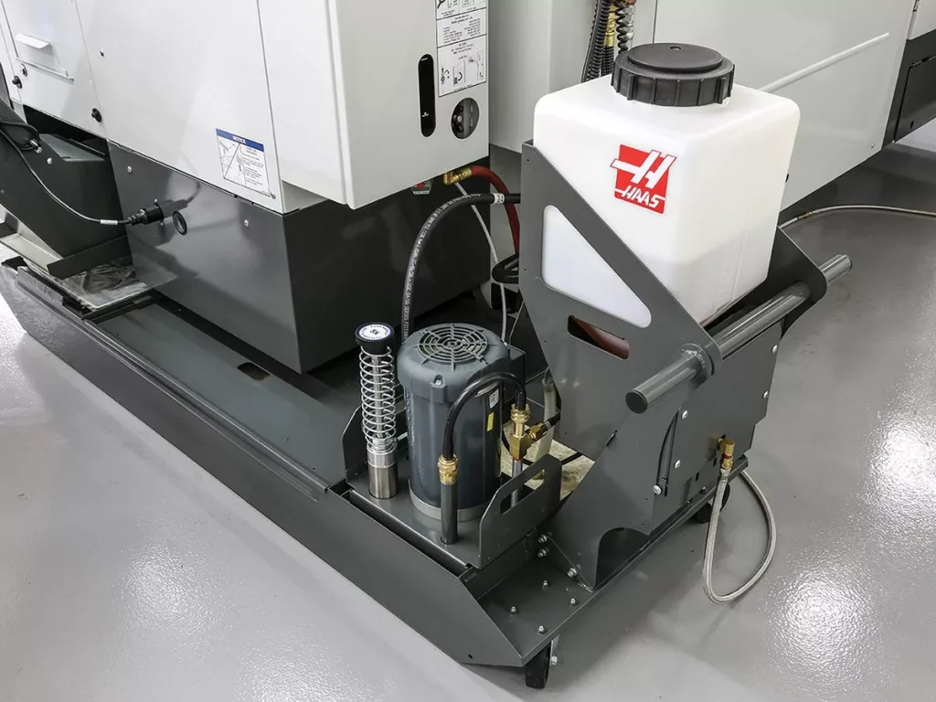
On any CNC milling machine, coolant, lubrication, and chip control are what keep accuracy high and downtime low. If you’re running production in the U.S. — from CNC steel parts to precision aluminum or Inconel machining — this is where reliability and tool life are won or lost.
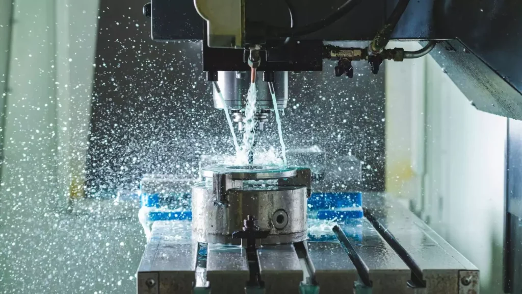
Coolant Delivery Systems: Flood, Mist, and Through-Spindle
The coolant system directly affects tool life, surface finish, and cycle time:
- Flood coolant
- Pumps a large volume of coolant over the cutting zone.
- Best for heavy metal removal, steel and stainless, and general-purpose CNC milling.
- Simple, low-cost, easy to maintain.
- Mist coolant
- Sprays a fine mist of coolant/air mix at the tool.
- Good for high-speed machining and light cuts, especially on aluminum and plastics.
- Lower coolant usage but needs proper ventilation.
- Through-spindle coolant (TSC)
- High-pressure coolant goes through the spindle and tool directly to the cutting edge.
- Ideal for deep holes, tough alloys, and precision CNC milling components.
- Reduces chip packing, improves tool life, and supports aggressive feeds and speeds.
If you’re machining higher-value parts or hard materials, a machine with reliable **through-spindle
Safety Features and Machine Enclosures on CNC Milling Machines
When we spec or build CNC milling machines, I treat safety features and enclosures as non‑negotiable components—just as critical as the spindle or axis drives.
Full Enclosure vs Open-Frame CNC Mills
For most U.S. shops, especially production or job shop work, a full enclosure CNC mill is the smart move.
| Feature | Full Enclosure CNC Mill | Open-Frame CNC Mill |
|---|---|---|
| Chip / coolant control | Excellent – chips and coolant stay inside | Poor – chips and splash go everywhere |
| Safety level | High – physical barrier to moving parts | Lower – more exposure to spindle & tools |
| Cleanup time | Faster – easy washdown and chip removal | Longer – floor, walls, and operator cleanup |
| Best use case | Production, heavy cuts, unattended cycles | Prototyping, training, light duty work |
If you’re running heavy CNC machining in steel or doing long unattended cycles, a fully enclosed machine will protect your people, cut cleanup time, and keep coolant where it belongs.
Safety Interlocks, Door Switches, and Light Curtains
Modern CNC milling machine components always include electronic safety interlocks tied to the doors and guards:
- Door interlock switches
- Prevent spindle start or axis motion when doors are open (or only allow slow jog).
- Stop the program if the operator opens a door during a cycle.
- Guard switches on chip conveyors and covers
- Shut down motion if a guard is opened.
- Protect maintenance staff during service.
- Light curtains (on some larger systems)
- Create a “no-go” zone around moving components.
- Stop motion instantly if someone breaks the beam.
These safety circuits are wired directly into safety relays and the CNC controller, not just to standard I/O, so they fail safe.
Emergency Stop Buttons and Safety Relays
Every CNC milling machine I sign off on must have clearly marked, easy-to-reach E‑Stop buttons:
- E‑Stop locations
- Operator panel (mandatory).
- Side or rear of the machine near loading areas.
- Optional pedestal or wall-mounted E‑Stop in high-traffic areas.
- Safety relays and circuits
- Cut power to servo drives and spindle drives immediately.
- Bring the machine to a safe stop without corrupting the CNC controller.
- Designed to default to “safe” if a wire breaks or a contact fails.
If you’re shopping for a new CNC or upgrading, don’t ignore the quality of the safety relay architecture—cheap controls can behave unpredictably during faults.
Operator Visibility and Ergonomic Controls
Safety isn’t just about stopping motion—it’s about letting the operator see clearly and work comfortably:
- High-visibility windows and LED lighting
- Large, coated windows so you can see the cut without opening the door.
- Bright internal LEDs so tool breakage or chip wrap is obvious.
- Ergonomic HMI and control panel layout
- Tilt and height-adjustable machine control panel (HMI).
- Large, clearly labeled buttons for cycle start, feed hold, E‑Stop.
- Manual pulse generator (handwheel) positioned for natural use.
- Access and reach
- Door openings sized so operators can load heavier fixtures safely.
- Table height and step access that don’t force awkward body positions.
Well-designed CNC machine guards and enclosures don’t slow you down—they actually let operators run faster, watch the process confidently, and keep the machine running longer with less risk.
If you’re planning higher-productivity or unattended work with complex fixturing, it’s worth pairing a well‑enclosed CNC with robust workholding and, when needed, rapid CNC machining support to dial in safe, repeatable setups from day one.
Maintenance of CNC Milling Machine Components
Staying on top of CNC milling machine maintenance is the only way to protect accuracy, uptime, and tool life. I treat maintenance as part of production, not an afterthought.
Daily Inspection Checklist for CNC Milling Machine Parts
Before and after each shift, I like to run a quick checklist on the main CNC milling machine components:
- Check the worktable and T-slots for chips, burrs, or rust. Wipe clean and apply a light protective oil if needed.
- Inspect spindle nose, tool holders, and pull studs for chips, wear, or fretting. Clean with a lint-free cloth.
- Verify coolant level and condition in the CNC coolant system—look for foam, odor, or contamination.
- Confirm lubrication indicators on the CNC lubrication system (no low-oil alarms, no obvious leaks).
- Walk around the machine base, column, and guards to spot loose fasteners, oil drips, or damage.
- Jog X, Y, Z axes and listen for abnormal noise in ball screws, linear guides, or servo drives.
The faster you catch issues in critical CNC milling machine parts, the cheaper they are to fix.
Cleaning, Lubrication, and Alignment Checks
Cleanliness and lubrication are what keep CNC milling components running smooth and tight:
- Cleaning
- Remove chips from table, fixtures, and tool changer after each job.
- Keep way covers, chip conveyor, and chip pans clear so nothing binds or floods.
- Lubrication
- Make sure ways, ball screws, and spindle bearings are getting the right oil/grease.
- Never override or disable automatic lubrication cycles.
- Alignment checks (weekly or monthly)
- Indicate the table and vises to spot twist or misalignment.
- Check spindle runout with a test bar if you see finish or tolerance drifting.
- Watch for uneven wear patterns on linear guides or dovetail ways.
If you’re running high-precision work, I recommend pairing this with a capable CNC milling parts partner that understands real-world tolerances, not just catalog specs.
Spindle, Axis, and Tool Holder Maintenance Best Practices
The spindle assembly, axis drive system, and tool holders do most of the precision work. I never cut corners here:
- Spindle
- Warm up the spindle daily (low RPM to high RPM program).
- Listen for changes in sound or vibration—often the first sign of spindle bearing issues.
- Keep the spindle taper clean; never use abrasive pads inside the taper.
- Axes (X, Y, Z and rotary axes)
- Monitor backlash and positioning errors; creeping backlash usually means worn ball screws or thrust bearings.
- Make sure linear guides are properly lubricated and free of dents or brinelling.
- Tool holders and collets
- Clean tapers, collets, and nuts regularly; replace worn ER collets and pull studs.
- Don’t over-tighten – follow torque specs for BT, CAT, and HSK tool holders.
- Inspect for fretting, rust, or nicks that can transfer error into the cut.
Well-kept spindle and axis components are a big reason our CNC precision machining components hold tight tolerances for demanding U.S. customers.
When to Replace Worn CNC Milling Components
Running worn CNC milling machine components “a little longer” usually costs more in scrap and downtime than the part itself. I look for:
- Spindle components
- Growing noise, heat, or vibration → likely spindle bearing wear.
- Poor surface finish that doesn’t improve with new tools or parameters.
- Axis drive and motion parts
- Measurable backlash that compensation can’t fully correct.
- Inconsistent positioning or lost steps on servo/stepper-driven axes.
- Workholding and table hardware
- Rounded or damaged T-slots, bolts, and nuts.
- Vises and fixtures that won’t repeat within spec.
- Tooling and ATC-related parts
- Tool holders that slip, stick, or fail to pull up consistently.
- ATC arm or drum misalignment causing frequent tool-change faults.
When any of these show up repeatedly, I plan a controlled replacement instead of waiting for a full breakdown—especially on key components that keep our CNC production machining running on schedule for U.S. customers.
How CNC Milling Machine Components Drive Machining Quality
When we talk about real CNC precision machining results in the U.S. market—tight tolerances, clean surface finish, and reliable repeatability—it all comes down to the quality of the core CNC milling machine components.
Spindle Rigidity = Surface Finish + Accuracy
The spindle assembly is the heart of the machine. If the spindle isn’t rigid, everything else struggles.
- High‑rigidity spindle = less chatter, better surface finish, tighter tolerances
- Quality spindle bearings = stable runout, better tool life, consistent dimensions
- Balanced tool holders (BT, CAT, HSK) = smoother cuts at higher RPM
- Good cooling and lubrication around the spindle = less thermal growth, more stable accuracy
If you’re chasing true CNC precision machining components for aerospace, medical, or tight-tolerance metal fabrication parts, invest in a stronger spindle, better bearings, and higher-quality tool holders.
Axis Drive Quality = Positioning and Repeatability
Your X, Y, and Z axis drive system (ball screws, linear guides, servo motors, and feedback devices) controls how precisely the machine moves.
- Precision ball screws and linear guides cut backlash and stick–slip
- Servo motors with encoders give high-resolution positioning vs. basic stepper motors
- Linear scales boost absolute accuracy and thermal compensation
- Rigid axis structure reduces deflection when cutting tough materials like CNC steel
Better axis components directly improve positioning accuracy, repeatability, and cycle time.
Workholding and Fixtures = Holding Tight Tolerances
Even with a perfect spindle and axis drive, poor workholding kills accuracy.
- Quality vices, clamps, and modular fixtures keep parts from shifting under load
- Ground worktable and T-slots ensure flat, repeatable setups
- Rotary tables and indexers need minimal backlash for multi-side machining
- Pallet systems help maintain consistent setups across production runs
If you’re making high-precision parts, workholding quality is just as critical as the machine itself. It’s a key piece of any serious precision and metrology strategy in manufacturing.
Choosing Machines and Upgrades By Components
When I evaluate CNC milling machines or upgrades for sheet metal machining, metal fabrication and bending, or CNC precision turned parts, I don’t just look at the brand—I look at the component stack:
Prioritize upgrades in this order:
- Spindle assembly – higher rigidity, better bearings, better tool retention
- Axis drive system – premium ball screws, linear guides, and servo drives
- Workholding system – precision vices, fixtures, rotary tables, pallet changers
- Feedback and control – encoders, linear scales, and a solid CNC controller
If your goal is better finish, tighter tolerances, and consistent repeatability, build your CNC milling machine around component quality—not just specs on a brochure.
FAQs About CNC Milling Machine Components
Most important CNC milling machine components
If you’re running jobs in the U.S. and care about uptime and accuracy, these CNC milling machine components matter most:
| Component Group | Key Parts to Know | Why It Matters |
|---|---|---|
| Spindle assembly | Spindle, bearings, motor, tool taper, drawbar | Power, surface finish, tool life |
| Axis drive system | Ball screws, linear guides, servo motors, encoders | Accuracy, repeatability, speed |
| CNC controller & HMI | Control unit, screen, buttons, handwheel | Programming, setup, troubleshooting |
| Workholding & table | T‑slots, vises, fixtures, rotary table, pallets | Part stability, cycle time, flexibility |
| Tooling & ATC | BT/CAT/HSK holders, collets, ATC arm/drum, magazine | Changeover time, reliability |
| Coolant & chip system | Flood/through‑spindle coolant, chip conveyor | Tool life, automation, cleanliness |
Vertical vs. horizontal mill components
Vertical milling machine components and horizontal milling machine parts share the same basics, but layout changes how they cut:
| Feature / Component | Vertical CNC Mill | Horizontal CNC Mill |
|---|---|---|
| Spindle orientation | Vertical (downwards) | Horizontal (sideways) |
| Main structure | Column, knee (on many VMCs), table | Column, base, integrated pallet/table |
| Chip evacuation | Harder; chips sit on the part/table | Easier; chips fall away from the cut |
| Workholding | Vises/fixtures on flat table | Tombstones, multi‑side fixtures, pallets |
| Best for | General job shop, 2.5D, light 3D work | High‑volume, multi‑face, heavy cutting |
Basic troubleshooting: axis, spindle, ATC
Keep it simple and systematic:
Axis issues (X/Y/Z, 4‑axis, 5‑axis):
- Backlash or poor accuracy: check gibs/ways, ball screw nuts, coupling, parameters.
- Vibration or noise: inspect linear guides, ball screws, look for contamination.
- Alarms or no movement: verify servo drives, encoders, limit switches, cabling.
Spindle problems:
- Overheating: check coolant and lubrication, spindle cooling system, belt tension.
- Noise or rough finish: inspect spindle bearings, tool holder taper, pull stud.
- Low power or stalls: check spindle drive, motor, and cutting parameters.
ATC (automatic tool changer) faults:
- Missed tool change: verify tool number call, magazine position.
- Tool drop / poor retention: inspect pull studs, drawbar force, grippers.
- Mechanical jams: clean chips, check sensors and air pressure for arm/drum type ATCs.
For tight-tolerance work and reliable uptime, I often pair milling with precision turning; if you need turned features with your milled parts, my CNC turning services can close that gap.
Best component upgrades for performance
If you’re upgrading a shop in the States and want the most gain per dollar, these CNC milling components usually move the needle first:
| Upgrade Area | What to Upgrade | Main Benefit |
|---|---|---|
| Tooling & holders | Balanced BT/CAT/HSK, ER collets, pull studs | Better surface finish, higher RPM |
| Workholding | Quality vises, modular fixtures, rotary table | Faster setups, better repeatability |
| Coolant & chips | Through‑spindle coolant, better chip conveyor | Tool life, longer unattended runs |
| Feedback & drives | Higher‑res encoders, better servo tuning | Accuracy, smoother motion |
| Spindle | Higher power or higher speed spindle | More materials, faster cycle times |
When I design cnc milling components and cnc precision machining components, I always balance cost, rigidity, and serviceability so U.S. shops can run hard without constant tweaking.