Introduction
The metal forming process is widely used in manufacturing to produce components ranging from simple brackets to structural frames and automotive panels. Unlike machining, which creates a part by removing material, metal forming changes the shape of a workpiece through controlled deformation while keeping most of the material intact. This difference makes forming an efficient option for many applications where the required geometry can be achieved without extensive material removal.
Selecting a forming process involves more than choosing between bending, stamping, or forging. Material properties, part geometry, dimensional requirements, production volume, and downstream manufacturing operations all influence whether forming is an appropriate solution. A process that works well for a thin sheet metal enclosure may not be suitable for a thick structural component, and a part that can be formed into its basic shape may still require machining to produce functional features.
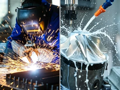
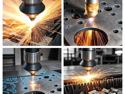
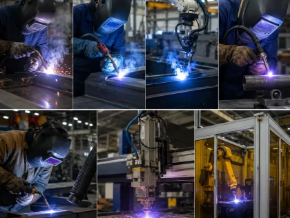
In practical manufacturing, metal forming is often one step within a broader production process rather than a standalone solution. Formed components may undergo welding, heat treatment, CNC machining, surface finishing, and inspection before becoming finished products. Understanding how these processes work together helps engineers make informed design decisions and supports more efficient production planning.
This article explains the common metal forming process methods, the material behavior behind forming, key design considerations, and the role of CNC machining in producing finished metal components.
What Is the Metal Forming Process?
The metal forming process refers to a group of manufacturing methods that reshape metal through plastic deformation. Instead of cutting away material, external force is applied until the metal permanently changes shape. Throughout this process, the material volume remains nearly constant, while its geometry is modified to meet the required design.
The ability to plastically deform metal depends on its mechanical properties. When the applied force exceeds the material’s yield strength, the metal no longer returns to its original shape after the load is removed. This permanent deformation allows manufacturers to create bends, curves, flanges, channels, and other geometries without significant material loss.
Because the process reshapes existing material, metal forming generally uses raw stock more efficiently than subtractive manufacturing. It is commonly applied to sheet metal, bars, tubes, and billets, depending on the forming method being used.
Although the principle appears straightforward, successful forming requires careful control of tooling, force, material behavior, and dimensional variation. Small changes in material thickness or mechanical properties can influence the final shape of a component.
Metal Forming, Metal Fabrication, and CNC Machining
These manufacturing terms are often used together, but they describe different aspects of production.
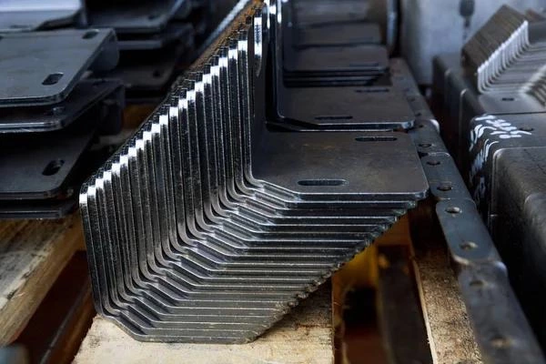
Metal forming focuses on reshaping material through deformation. Processes such as bending, rolling, stamping, and forging all belong to this category.
Metal fabrication is a broader manufacturing concept that includes forming as well as cutting, welding, machining, and assembly. A fabricated component may go through several different manufacturing stages before completion.
CNC machining is a material removal process that produces precise dimensions by removing metal with computer-controlled cutting tools. It is typically selected when components require features that cannot be achieved through forming alone, such as threaded holes, precision pockets, bearing seats, or tight-tolerance mounting surfaces.
Rather than competing with one another, these manufacturing methods often complement each other. Forming creates the overall shape efficiently, while machining provides the dimensional accuracy needed for functional features.
Material Behavior During the Metal Forming Process
Understanding how metals respond to forming forces is essential when selecting a manufacturing process. Different materials behave differently under load, and these differences influence both manufacturability and final part quality.
Rather than considering forming only as a shaping operation, engineers also evaluate how deformation affects mechanical properties, dimensional stability, and the likelihood of defects.
Yield Strength and Plastic Deformation
Every metal has an elastic range in which it temporarily changes shape under load. If the force is removed before reaching the yield point, the material returns to its original dimensions.
The metal forming process operates beyond this elastic range. Once the applied stress exceeds the yield strength, permanent deformation begins, allowing the material to retain its new shape after the load is released.
Different materials have different yield strengths, which means the forming force must be selected according to the material being processed. Materials with higher strength generally require greater forming forces and may place higher demands on tooling and equipment.
This relationship also explains why manufacturing parameters cannot simply be transferred from one material to another without adjustment.
Ductility and Formability
Ductility describes a material’s ability to deform without cracking. It is one of the most important characteristics affecting formability.
Materials with higher ductility can generally undergo larger shape changes before failure, making them suitable for operations involving significant deformation.
Aluminum alloys, for example, are widely used because many grades combine relatively low weight with good formability. Stainless steel provides excellent corrosion resistance but often requires greater forming force because of its higher strength and work-hardening behavior. High-carbon steels may offer increased hardness but typically have lower formability than mild steel.
Material selection therefore influences not only the final performance of a component but also the manufacturing process required to produce it.
Springback and Dimensional Control
One characteristic that distinguishes metal forming from many other manufacturing methods is springback.
After forming pressure is removed, the material tends to recover part of its elastic deformation. As a result, the finished angle or radius may differ slightly from the tooling geometry.
The amount of springback depends on several factors, including:
- Material properties
- Material thickness
- Bend radius
- Forming method
Manufacturers typically account for springback during tooling design or process setup so that the finished component reaches the intended dimensions.
For parts with strict dimensional requirements, additional CNC machining may still be necessary after forming to achieve accurate functional surfaces.
Grain Flow and Mechanical Properties
Plastic deformation also changes the internal grain structure of a metal.
During forming, the grains tend to elongate and align with the direction of material flow. This change can influence mechanical behavior, particularly in processes such as forging, where controlled grain flow contributes to the strength of the finished component.
The effect varies depending on the material and the amount of deformation involved. Understanding grain flow helps engineers select manufacturing methods that support both structural performance and dimensional requirements.
Common Types of Metal Forming Processes
The term metal forming process covers several manufacturing methods, each designed for different materials, geometries, and production requirements. Although these processes all rely on plastic deformation, the way force is applied and the resulting part characteristics differ considerably.
Selecting the appropriate method depends on more than the final shape. Material thickness, production volume, tooling investment, and downstream operations all influence the decision.
Bending
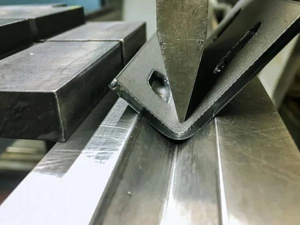
Bending is one of the most widely used forming methods, particularly for sheet metal fabrication.
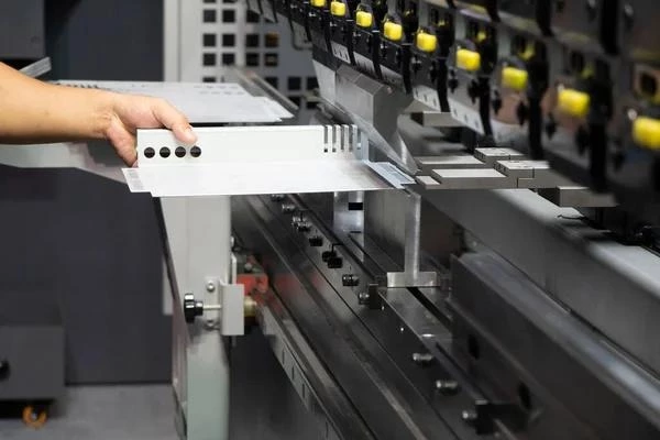
The process applies controlled force along a straight line to produce a permanent angle or profile. Press brakes are commonly used because they can produce a wide variety of bend angles with relatively flexible tooling.
Bending is frequently applied to components such as:
- Brackets
- Equipment enclosures
- Electrical cabinets
- Mounting plates
- Structural supports
Several factors influence bending quality, including material thickness, bend radius, tooling geometry, and springback. Sharp bends may increase stress concentration, while bends that are too close to holes or cutouts can lead to distortion during forming.
For components requiring accurate hole positions or precision mounting surfaces, bending is often followed by CNC machining to achieve the required tolerances.
Stamping
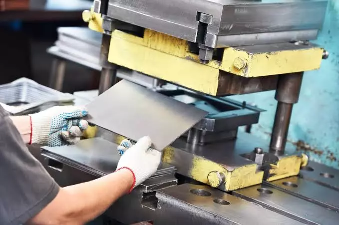
Stamping reshapes sheet metal using dedicated dies installed in mechanical or hydraulic presses.
Unlike bending, which typically creates one or several angles, stamping can produce more complex geometries in a single press stroke. Depending on the tooling design, the process may include piercing, blanking, embossing, or shallow forming operations.
Because tooling is designed specifically for a particular part, stamping is commonly selected for medium- to high-volume production where the tooling cost can be distributed across a large number of components.
The process provides good consistency between parts once production is established, but design changes after tooling has been manufactured may require modifications or replacement of the dies.
Common Types of Metal Forming Processes
Deep Drawing
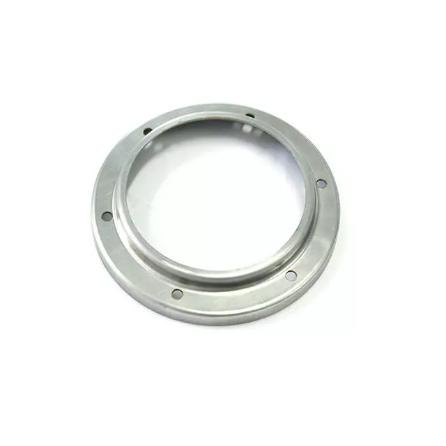
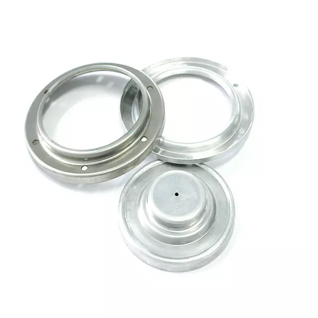
Deep drawing is a forming process used to produce hollow components from flat sheet metal. During the operation, a punch forces the sheet into a die cavity, allowing the material to flow inward and form a three-dimensional shape.
The process is commonly used for parts with a relatively large depth compared with their diameter, including:
- Cylindrical housings
- Metal containers
- Battery cases
- Automotive body components
- Kitchen sinks
Unlike simple bending, deep drawing requires careful control of material flow. If the material cannot move evenly into the die, defects such as wrinkling, tearing, or excessive thinning may occur.
Material ductility, lubrication, blank holder force, and die design all influence the outcome. For this reason, process parameters are typically optimized according to both the material and the part geometry.
Although deep drawing can produce complex shapes efficiently, it is generally less suitable for parts that require numerous precision features. Holes, threads, sealing surfaces, and critical interfaces are often added later through secondary machining operations.

Roll Forming
Roll forming is a continuous manufacturing process that gradually shapes sheet metal by passing it through a sequence of rollers.
Rather than producing the final geometry in a single operation, each roller set introduces a small amount of deformation until the required profile is achieved.
This approach is commonly used for long components with a consistent cross-section, such as:
- Structural channels
- Rails
- Roof panels
- Window frames
- Cable trays
Because deformation occurs progressively, roll forming can maintain relatively stable dimensions over long production runs while reducing localized stress within the material.
However, the process is limited to profiles with uniform cross-sections. Components containing complex three-dimensional features, localized pockets, or varying thicknesses generally require additional manufacturing operations.
Forging
Forging is another important metal forming process, although its manufacturing principles differ from sheet metal forming.
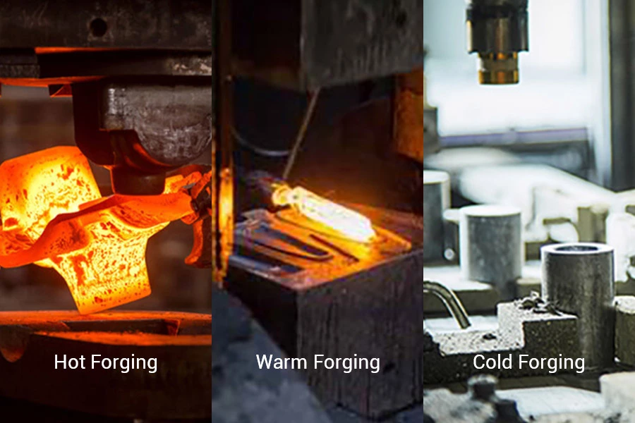
Instead of reshaping thin sheet material, forging applies compressive force to solid metal stock. Depending on the application, the workpiece may be formed at elevated temperatures or under cold-working conditions.
Common forging methods include:
- Open-die forging
- Closed-die forging
- Upset forging
- Roll forging
Forging is often selected for components that require high mechanical strength because the deformation process refines the material structure and aligns the grain flow with the part geometry.
Typical forged components include:
- Shafts
- Connecting rods
- Gears
- Flanges
- Heavy-duty mechanical parts
Despite the near-net shape achieved through forging, many forged parts still require CNC machining. Features such as bearing seats, precision bores, threaded holes, and mating surfaces generally cannot be produced to final dimensional requirements during the forging operation alone.
Hot Forming vs. Cold Forming
Temperature plays an important role in metal forming because it directly affects material behavior during deformation.
Manufacturers generally select either hot forming or cold forming based on the material, component geometry, mechanical property requirements, and production objectives.
Neither approach is universally suitable. Each has advantages and limitations that should be evaluated according to the application.
Cold Forming
Cold forming is performed at or near room temperature.
Because the material is not heated before deformation, dimensional consistency is often easier to maintain than in high-temperature forming processes. Surface oxidation is also minimized, reducing the need for additional cleaning before subsequent manufacturing operations.
Cold forming is commonly used for:
- Sheet metal brackets
- Electronic enclosures
- Precision stampings
- Fasteners
- Small structural components
However, deforming material at lower temperatures requires higher forming forces. As deformation increases, some materials also experience work hardening, making further forming operations more difficult.
These characteristics influence tooling design, equipment selection, and production planning.
Hot Forming
Hot forming is carried out after heating the material to a temperature where it becomes easier to deform.
Reducing the material’s resistance to deformation allows manufacturers to produce larger shape changes while lowering the required forming force.
Hot forming is frequently applied to:
- Thick steel sections
- Large forged components
- High-strength alloys
- Complex structural parts
Although elevated temperatures improve formability, they also introduce additional manufacturing considerations.
Heating can cause:
- Surface oxidation
- Scale formation
- Thermal expansion
- Cooling-related dimensional variation
Because of these effects, hot-formed components often require machining after forming to achieve the final dimensions specified on engineering drawings.
Selecting Between Hot and Cold Forming
The choice between hot and cold forming depends on balancing manufacturing efficiency with product requirements.
Factors commonly considered include:
- Material type
- Part size
- Required geometry
- Mechanical properties
- Dimensional tolerance
- Production quantity
For example, components with relatively simple bends in thin sheet metal are commonly produced through cold forming. Large forged mechanical parts, on the other hand, may benefit from hot forming because the material can undergo greater deformation without excessive forming force.
The manufacturing process should be evaluated as a whole rather than selecting a forming method based solely on one characteristic.
Materials Commonly Used in the Metal Forming Process
Material selection influences every stage of the metal forming process, from tooling requirements to dimensional accuracy and subsequent machining operations.
Each metal responds differently to deformation because of differences in strength, ductility, hardness, and work-hardening behavior.
Aluminum
Aluminum is widely used in forming applications because many aluminum alloys offer good ductility while maintaining a relatively low weight.
Common applications include:
- Transportation equipment
- Consumer products
- Electronic enclosures
- Aerospace structures
Some aluminum alloys are easier to form than others. Material grade and heat treatment condition should therefore be considered during process planning.
Carbon Steel
Carbon steel remains one of the most commonly formed engineering materials.
Its balance of strength, availability, and manufacturing flexibility makes it suitable for structural components, industrial equipment, and fabricated assemblies.
Different carbon contents influence both formability and mechanical properties. Mild steels generally provide greater formability, while higher carbon steels require greater attention during forming because they become less ductile.
Stainless Steel
Stainless steel combines corrosion resistance with good mechanical performance, making it suitable for many industrial applications.
Compared with mild steel, however, stainless steel often exhibits greater work hardening during deformation.
As a result, forming operations may require:
- Higher forming forces
- More robust tooling
- Careful process control
Springback is also more noticeable for many stainless steel grades, requiring compensation during tool design or process setup.
Copper and Brass
Copper and brass are frequently selected when electrical conductivity, thermal conductivity, or appearance is important.
These materials generally exhibit good formability, allowing manufacturers to produce intricate shapes with relatively low forming forces.
Applications include:
- Electrical connectors
- Decorative components
- Heat transfer equipment
Material selection should still consider downstream manufacturing processes, particularly when machining, welding, or surface finishing will follow.
Design Considerations for the Metal Forming Process
A successful forming process begins long before production starts.
The design stage influences manufacturability, tooling complexity, dimensional stability, and production efficiency. Small changes to part geometry can significantly affect how a component behaves during forming.
Understanding these relationships helps reduce unnecessary manufacturing challenges while improving consistency during production.
Bend Radius
Every material has practical limits regarding how sharply it can be bent.
If the bend radius is too small for the selected material, excessive strain may develop on the outer surface of the bend, increasing the possibility of cracking.
Larger bend radii generally reduce forming stress, although they may not always satisfy functional or space requirements.
Selecting an appropriate bend radius therefore requires balancing material behavior with product design.
Material Thickness
Material thickness influences nearly every aspect of the forming process.
Thicker materials require greater forming force and more rigid tooling. They also tend to exhibit different springback characteristics than thinner materials.
When multiple part thicknesses are introduced into production, tooling and process parameters may need adjustment to maintain dimensional consistency.
Design Considerations for the Metal Forming Process
Hole Placement Relative to Bend Lines
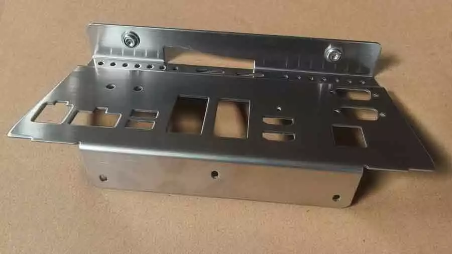
The location of holes, slots, and cutouts should be considered during the design stage rather than after tooling has been finalized.
Features positioned too close to a bend line may deform as the material flows during forming. Depending on the material and bend geometry, holes may become elongated, while nearby edges can experience localized distortion.
To reduce these effects, engineers often establish minimum distances between bends and adjacent features based on the material thickness and forming method. Although these recommendations vary between applications, allowing sufficient space generally improves dimensional consistency and reduces the likelihood of secondary corrections.
When hole position is critical for assembly, manufacturers may choose to machine the holes after forming instead of producing them beforehand.
Springback Compensation
Springback is one of the most common challenges in the metal forming process. After the forming load is removed, part of the elastic deformation is recovered, causing the final angle or profile to differ slightly from the tooling geometry.
The amount of springback depends on several factors, including:
- Material strength
- Material thickness
- Bend radius
- Forming method
- Tool geometry
Rather than treating springback as a defect, manufacturers typically account for it during process development. Tooling may be designed with an overbend angle, or forming parameters may be adjusted until the finished part consistently meets the required dimensions.
For components with demanding dimensional requirements, springback compensation alone may not achieve the required accuracy. In these situations, secondary machining can be used to produce the final functional surfaces.
Designing for Secondary Operations
Not every feature should be created during the forming operation.
Although forming is effective for producing the overall shape of a component, certain features are better created afterward. Incorporating these requirements early in the design stage helps avoid unnecessary process complexity.
Features commonly produced after forming include:
- Precision holes
- Threads
- Bearing seats
- Counterbores
- Flat reference surfaces
- Tight-tolerance locating features
Attempting to form these features directly may increase tooling complexity without providing corresponding manufacturing benefits.
Separating structural forming from precision machining often results in a more practical manufacturing sequence.
When Is CNC Machining Required After the Metal Forming Process?
Forming establishes the geometry of a component, but geometry alone is not always enough to satisfy functional requirements.
Many parts must interface with bearings, shafts, fasteners, sealing elements, or other precision components. These interfaces frequently require dimensional control beyond what forming alone can consistently achieve.
For this reason, CNC machining is commonly used as a secondary manufacturing process.
Improving Dimensional Accuracy
Forming processes are influenced by material variation, elastic recovery, tooling wear, and manufacturing conditions. Even when these factors are carefully controlled, dimensional variation may still occur.
CNC machining provides an additional level of control by removing small amounts of material to achieve the dimensions specified on the engineering drawing.
This approach is commonly applied to:
- Mounting surfaces
- Reference faces
- Alignment features
- Precision bores
Instead of relying on forming to produce every critical dimension, manufacturers often allow the forming process to create the overall geometry before machining only the features that require greater accuracy.
Producing Functional Features
Many functional features cannot be created directly during forming because they require precise cutting geometry or controlled positional accuracy.
These include:
- Internal threads
- Reamed holes
- Counterbores
- Countersinks
- Precision slots
- Bearing fits
CNC machining allows these features to be produced after the basic shape has already been established.
This sequence separates structural manufacturing from precision finishing, making each process responsible for the tasks it performs most effectively.
Refining Welded or Formed Assemblies
Some fabricated components combine forming with welding before final machining.
During welding, localized heating and cooling can introduce dimensional changes or residual stress within the assembly. Depending on the design, these changes may influence flatness, hole position, or alignment.
Instead of machining each individual component before assembly, manufacturers often complete the forming and welding operations first, followed by machining the critical interfaces after the assembly has stabilized.
This sequence helps ensure that functional features are referenced from the completed structure rather than from individual parts before joining.
Quality Control in the Metal Forming Process
Inspection is an important part of the manufacturing process because it verifies whether the finished component conforms to design requirements.
Quality control begins with the incoming material and continues through forming, machining, finishing, and final inspection.
The inspection methods selected depend on the complexity of the component and its intended application.
Dimensional Inspection
Dimensional inspection verifies whether the formed component matches the specified geometry.
Measurements may include:
- Overall dimensions
- Bend angles
- Hole locations
- Flatness
- Profile dimensions
Simple components may be inspected using calipers, height gauges, or dedicated fixtures, while more complex parts may require coordinate measuring machines (CMMs) to verify critical features.
Surface Inspection
The forming process can introduce surface imperfections if process parameters are not properly controlled.
Inspection may identify conditions such as:
- Surface scratches
- Cracks
- Wrinkles
- Tool marks
- Edge deformation
Detecting these conditions early helps prevent unnecessary downstream processing.
Material Verification
Material verification confirms that the correct alloy, thickness, and material condition are used before production begins.
This step is particularly important when different material grades have similar appearances but different mechanical properties.
Selecting the appropriate material supports both forming performance and the functional requirements of the finished component.
Choosing the Right Manufacturing Process
Selecting a manufacturing process involves evaluating the complete production requirement rather than focusing on a single operation.
Several factors influence this decision.
Part Geometry
Simple bends and uniform profiles may be well suited to forming processes.
Components containing intricate three-dimensional features or precision interfaces often require machining in addition to forming.
Material Characteristics
Different materials respond differently to deformation and machining.
Understanding these characteristics helps determine whether forming, machining, or a combination of both is more appropriate.
Production Volume
Production quantity influences process selection because some forming methods require dedicated tooling.
For low-volume production or prototype development, flexible manufacturing methods such as CNC machining may reduce tooling investment.
As production volume increases, forming processes with dedicated tooling may become more economical.
Dimensional Requirements
Not every dimension requires the same level of accuracy.
Structural dimensions may be produced through forming, while critical assembly features can be machined afterward.
Matching the manufacturing process to the functional requirements of each feature often leads to a more efficient production strategy.
Why Metal Forming and CNC Machining Are Often Used Together
Metal forming and CNC machining serve different purposes within the manufacturing process.
Forming creates the primary shape of a component with efficient material utilization, while CNC machining refines selected features that require greater dimensional control.
Rather than viewing these processes as alternatives, they are often planned as complementary manufacturing steps.
A formed component may require machined mounting surfaces for assembly, while a forged part may require precision bores before installation. Similarly, sheet metal assemblies may undergo machining after welding to ensure alignment between mating components.
Selecting the appropriate sequence depends on the part geometry, functional requirements, and manufacturing objectives rather than on a single process preference.
Frequently Asked Questions
What is the metal forming process?
The metal forming process reshapes metal through plastic deformation without removing significant amounts of material. Common forming methods include bending, stamping, rolling, deep drawing, and forging.
What is the difference between metal forming and CNC machining?
Metal forming changes the shape of a workpiece by applying force, while CNC machining removes material using computer-controlled cutting tools to create precise dimensions and functional features.
Which metals are commonly used in metal forming?
Aluminum, carbon steel, stainless steel, copper, and brass are among the materials frequently used in metal forming. The appropriate material depends on factors such as strength, ductility, corrosion resistance, and application requirements.
Does the metal forming process affect material properties?
Yes. Plastic deformation can change grain orientation, residual stress, and mechanical behavior. The extent of these changes depends on the material, the forming method, and the amount of deformation.
Why do formed parts often require CNC machining?
Forming efficiently creates the overall geometry of a component, but some functional features require greater dimensional control. CNC machining is commonly used to produce precision holes, threads, reference surfaces, and other critical features after the forming process.
Conclusion
The metal forming process encompasses a range of manufacturing methods that reshape metal through controlled plastic deformation. Bending, stamping, deep drawing, roll forming, and forging each serve different production requirements, and the most appropriate method depends on factors such as material behavior, part geometry, production volume, and performance expectations.
Although forming can efficiently create the primary shape of a component, it is often one stage within a broader manufacturing workflow. Operations such as CNC machining, welding, heat treatment, surface finishing, and inspection may follow to meet the functional and dimensional requirements of the finished part.
Understanding how forming interacts with these downstream processes allows engineers and manufacturers to develop production strategies that balance manufacturability, accuracy, and cost while meeting the technical requirements of the application.