
CNC Machining Tolerance Guide for Precision Parts
Your quick-reference guide to standard CNC tolerances, helping engineers optimize designs for prototyping, custom manufacturing, and strict quality control.
General Tolerances
& Material Shrinkage
& Part Distortion
First Article Inspection
What Is CNC Machining Tolerances?
CNC machining tolerances are simply the small range a finished part is allowed to vary from the drawing size and still be usable. In real production, no matter how stable the machine is, there will always be slight differences from tool wear, material, or setup. From shop experience, most issues don’t come from the overall accuracy, but from a few key dimensions that were either specified too tight or not controlled enough for assembly. In many cases, ±0.1 mm is already sufficient for general features, while only functional fits need tighter control. Once tolerance gets tighter, everything becomes slower and more expensive, so it’s always a balance between function, cost, and what actually matters on the part.
Standard CNC Machining Tolerance Table
CNC Machining Tolerance Table | Standard vs Precision vs High Precision
Typical achievable tolerance ranges for different precision levels and applications in real CNC production.
CNC Machining Tolerance Grades
| Tolerance Grade | mm | inch | Applications | Cost |
|---|---|---|---|---|
| Standard | ±0.10 ~ ±0.20 | ±0.004 ~ ±0.008 | Structural parts, enclosures | Low |
| Precision | ±0.05 ~ ±0.10 | ±0.002 ~ ±0.004 | Functional fits, mechanical parts | Medium |
| High Precision | ±0.01 ~ ±0.025 | ±0.0004 ~ ±0.001 | Aerospace, medical, optical parts | High |
CNC Process Tolerance Comparison
| Process | Standard | Precision | High Precision |
|---|---|---|---|
| CNC Milling Machining | ±0.10~0.20 | ±0.05~0.10 | ±0.01~0.025 |
| CNC Turning Machining | ±0.10~0.15 | ±0.05 | ±0.01~0.02 |
| 5-Axis Machining | ±0.10~0.15 | ±0.03~0.08 | ±0.008~0.02 |
Milling Tolerance
CNC Milling Tolerance Guide
Typical achievable tolerances in CNC milling and key factors affecting accuracy.
Typical CNC Milling Tolerance Ranges
| Machine Type | Standard Tolerance | Precision Tolerance | High Precision Tolerance | Best Use Cases |
|---|---|---|---|---|
| 3-Axis Milling | ±0.10 ~ ±0.20 mm | ±0.05 ~ ±0.10 mm | ±0.02 ~ ±0.05 mm | General parts, flat surfaces, pockets, structural components |
| 5-Axis Milling | ±0.05 ~ ±0.15 mm | ±0.02 ~ ±0.05 mm | ±0.008 ~ ±0.025 mm | Complex geometries, aerospace parts, medical implants, turbine blades |
Key Factors Affecting Milling Accuracy
- Tool deflection: long tools reduce accuracy
- Tool wear causes dimensional drift
- Spindle runout (≤0.002mm is critical)
- Tool holder rigidity and clamping force
- L/D ratio control for stability
- Machine expansion causes dimensional shift
- Cutting heat builds up in hard materials
- Coolant temperature stability matters
- Ambient fluctuation affects precision
- Warm-up cycle before machining
- Material hardness & stress release
- Thin walls deform under cutting force
- Large parts harder to control tolerance
- Deep cavities increase vibration risk
- Aluminum & plastics expand more easily
- Machine frame stiffness determines accuracy
- Fixture stability is critical for repeatability
- Backlash and calibration affect precision
- Multi-setup alignment introduces error
- Zero-point repeatability matters
- Feed rate & spindle speed balance
- Finishing strategy defines final accuracy
- Toolpath optimization reduces error
- 5-axis reduces setup accumulation error
- Adaptive machining improves stability
Turning Tolerance
CNC Turning Capability & Real-World Tolerance Range
CNC turning is generally more stable than milling for cylindrical parts, but actual tolerance depends heavily on setup rigidity, tool overhang, and workpiece geometry.
| Turning Feature | Typical Tolerance Range | Real Shop Floor Limitation |
|---|---|---|
| Outer Diameter (OD) | ±0.02 – ±0.05 mm | Tool wear and thermal drift over long production runs |
| Inner Diameter (Boring) | ±0.03 – ±0.08 mm | Boring bar deflection and vibration in deep holes |
| Shaft Length / Facing | ±0.05 – ±0.10 mm | Bar feeder repeatability and turret positioning accuracy |
| Concentricity | ≤ 0.01 – 0.03 mm | Re-chucking and multi-operation setup misalignment |
| Roundness | ≤ 0.005 – 0.02 mm | Chuck pressure deformation and spindle runout |
Shop Floor Insight
In real production, turning tolerance is usually limited by setup rigidity rather than machine specification. Long slender parts are especially sensitive to vibration, and even small changes in tool overhang or chuck pressure can shift dimensions beyond nominal tolerance.
What CNC Capability Limit Really Means in Production
In real CNC production, capability limit is not defined by a single number on paper. It is the point where a process can still meet tolerance, but only with tighter control on setup, tool condition, and temperature stability.
How We Define Capability Limit on the Shop Floor
In actual machining practice, capability limit is the point where production shifts from “stable running” to “controlled running”. Inside this range, parts can be produced repeatedly with minimal adjustment. Once we approach the limit, operators need to monitor tool wear more frequently, control cutting parameters more tightly, and sometimes inspect parts during the process instead of only at the end.
| Production Zone | Tolerance Range | Reality in Production |
|---|---|---|
| Stable Capability Zone | ±0.05 – ±0.10 mm | This is the normal production range. Machines run steadily, tool wear impact is predictable, and only final inspection is usually required. |
| Controlled Capability Zone | ±0.01 – ±0.03 mm | At this level, small variations start to show up. Operators often need to adjust feeds, monitor tool wear, and check critical dimensions during machining. |
| Capability Limit Zone ⭐ | ±0.001 – ±0.01 mm | This is the real limit in production. It is achievable, but only when machine condition, tool life, temperature, and fixturing are all tightly controlled. Even small drift can cause out-of-spec parts. |
What Makes It a “Limit”
It becomes a limit when the process no longer runs “freely”. Every batch may require fine adjustment, and tool condition becomes a key variable. Even small changes in material batch, temperature, or clamping force can directly affect final dimensions.
Why It Is Not Stable in Mass Production
At this level, machining is no longer purely standard production. It becomes process-controlled manufacturing. Output is still possible, but consistency depends heavily on operator attention, inspection frequency, and real-time process adjustment.
Shop Floor Insight
In real CNC machining, capability limit is not a hard boundary. It is the point where cost, risk, and process sensitivity increase faster than the benefit of tighter tolerance. This is why capability is judged by long-term stability across batches, not by a single successful part.
Material Factor
Material Impact on Machining Tolerance
In real CNC production, material behavior often has a more direct impact on dimensional stability than theoretical specifications. Heat buildup, clamping deformation, tool wear, and internal stress release all show up during actual machining.
Aluminum
One of the most stable materials in daily shop-floor machining. Cutting is smooth and predictable. In production, dimensional drift usually only appears in thin-wall parts or long machining cycles due to heat accumulation.
Stability: High — consistent and easy to control in production
Stainless Steel
Tends to generate heat and work harden during cutting. In real production, stability is strongly affected by tool condition, cutting depth, and cooling strategy, especially for deep or long engagement cuts.
Stability: Medium — sensitive to heat and tool wear
Carbon Steel / Mild Steel
Generally stable and widely used in production. As long as cutting parameters and tool wear are controlled, dimensional consistency is predictable across batches.
Stability: High–Medium — balanced machining behavior
Brass / Copper
Very easy to machine with low cutting force and stable chip formation. In shop-floor practice, dimensional variation is usually minimal, making it suitable for precision fittings and electrical parts.
Stability: High — very predictable machining behavior
Engineering Plastics
Materials like POM, Nylon, and PTFE are sensitive to heat and stress release. In real machining, parts may slightly deform after unclamping, so finishing strategy and allowance control are critical.
Stability: Low–Medium — affected by heat and elastic recovery
Titanium & Exotic Alloys
Difficult materials in real production. Heat concentrates at the cutting edge, tool wear is fast, and dimensional drift can appear quickly if process control is not tight.
Stability: Low — requires strict process control
In real CNC machining, material selection is always evaluated together with part geometry, fixturing method, and process stability. The same tolerance requirement can behave very differently depending on these conditions.
CNC Machining Tolerance Levels With Real Production Examples
Different tolerance levels behave differently depending on geometry, material, and machining setup. Below are real production cases commonly seen in CNC machining.
±0.05 mm — Stable Production Range
This range is typically used where geometry is not highly sensitive to small variations. It performs very consistently across most materials.
Common real parts:
- • Aluminum housing covers with multiple machining features
- • Mechanical brackets with bolt-hole patterns
- • Structural support frames with non-critical alignment
- • Enclosures where function is not affected by minor deviation
±0.01 mm — Controlled Fit Features
At this level, small changes in setup or tool wear can already be reflected in measurement. It is commonly used for mating and alignment functions.
Common real parts:
- • Shaft-to-bearing fit diameters
- • Precision dowel pin locating holes
- • Multi-hole alignment patterns for assembly
- • Sliding or rotating mechanical interfaces
±0.005 mm — Critical Functional Interfaces
This level is not defined by machine capability alone—it depends heavily on temperature control, tool condition, and how many times the part is repositioned during machining.
Typical real applications:
- • High-speed rotating shaft journals
- • Sensor or optical alignment seats
- • Precision valve sealing surfaces
- • Aerospace-grade interface components
- • Medical device precision assemblies
- • Multi-part stack alignment systems
Production Insight
In real machining projects, tolerance selection is usually driven by assembly function and cost balance rather than pushing every feature to the tightest possible value. Most production parts combine different tolerance levels depending on functional importance.
How We Control CNC Machining Accuracy in Real Production
In CNC machining, accuracy is not guaranteed by machines alone. It is maintained through continuous inspection, process verification, and structured quality control at every production stage.
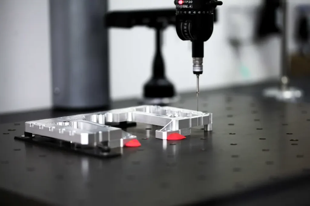
CMM Inspection (Coordinate Measuring Machine)
Used for high-precision dimensional verification. We rely on CMM to confirm critical features such as position, concentricity, and geometric tolerances, especially for tight tolerance parts or complex geometries.
Micrometer & Caliper Measurement
Used for routine in-process inspection. Operators measure key dimensions during machining to ensure the process stays within control before final inspection.
First Article Inspection (FAI)
The first produced part is fully inspected before mass production starts. This step ensures setup, tooling, and program are all correct before releasing the batch.
Quality Control Workflow
Incoming material check → first article inspection → in-process measurement → final inspection → shipment approval. Each step is designed to prevent deviation before it becomes a batch issue.
Shop Floor Insight
In real CNC production, most quality issues are not caused by a single bad part, but by process drift over time. That is why inspection is not treated as a final step, but as part of the production loop to keep variation under control.
What Affects Tolerance Stability in Real CNC Production
In actual machining, tolerance variation is usually caused by how the part reacts during clamping, cutting load, and setup changes—not just machine capability.
Thin Parts After Clamping Release
A common situation in production is that the part measures correct while it is still clamped, but shifts slightly after removal. This usually comes from internal stress or uneven clamping force.
In practice, operators will re-check key dimensions after unclamping, and if needed, apply a light finishing pass to stabilize the final size.
Deep Machining and Tool Vibration
When the tool extends deep into a bore or cavity, vibration becomes more noticeable during cutting. This directly affects roundness and internal surface consistency.
The usual approach is to remove material in stages, leaving a small finishing allowance for the final pass instead of cutting to size in one step.
Re-Clamping and Axis Shift
Once a part is taken out and reloaded into the chuck, even a small alignment difference can affect concentricity and position accuracy.
For tighter tolerance features, critical surfaces are typically finished in a single setup to avoid stack-up error from re-positioning.
Excessive Tight Tolerances on One Drawing
When too many features require tight tolerances, machining time increases and process control becomes more sensitive to tool wear and setup variation.
In production, tighter control is normally focused on functional interfaces such as mating fits, sealing areas, and alignment features.
Shop Floor Insight
In CNC machining, most tolerance deviation is not random—it follows predictable behavior based on clamping condition, tool rigidity, and setup changes. Once these factors are controlled, dimensional consistency becomes much more stable across batches.
FAQ
CNC Machining Tolerance FAQs
Quick answers based on real CNC machining experience in production environments.
What is standard CNC machining tolerance?
Standard CNC machining tolerance is typically around ±0.05 mm. In real production, this range is commonly used for general mechanical parts where small dimensional variation does not affect assembly or function.
How precise can CNC machining be?
In stable production conditions, CNC machining can reach around ±0.01 mm reliably. With strict process control, temperature stability, and careful fixturing, some critical features can achieve even tighter tolerances.
What affects CNC machining accuracy?
Accuracy is mainly affected by material behavior, tool wear, clamping stability, machine condition, and part geometry. In practice, most deviation comes from deformation during cutting or slight setup variations between operations.
Is ±0.01 mm possible in CNC machining?
Yes, ±0.01 mm is achievable in CNC machining for controlled features such as shafts, precision holes, and alignment surfaces. It requires stable fixturing, consistent tool condition, and careful process control during production.
Milling vs turning tolerance difference?
Turning generally achieves more consistent cylindrical tolerances because the part rotates in a stable axis. Milling relies on multi-axis tool movement, which introduces slightly more variation on round features, especially at tight tolerances.
How to reduce CNC machining cost?
The most effective way to reduce cost is to avoid applying tight tolerances to non-functional features, simplify geometry where possible, and design parts that can be machined in fewer setups. In production, setup time and inspection effort usually have more impact than cutting time itself.